how to pump down ac unit

Can I Install Ductless AC By Myself? My Thermostat Works And The Outside Unit Is Working, But The Inside Unit Won't Blow Air Into The House. What Can I Do A Couple Of The Bedrooms Are Hotter In The Summer Than The Rest Of The House And Colder In The Winter, What Can I Do? I Replaced A Compressor On An Old 1.5 Ton Rheem, The Compressor Won't Come On And Has Power To It How Do I Remove AC Clutch And Pulley From Compressor? Mansfield Office & Showroom: 08456 800 410 Crawley: 08456 590 022 Panasonic Pump Down System Panasonic’s two new innovative leak detection and pump down solutions have already made an impact, earning a spot on the shortlist for the ACR News & National ACR Product of the Year Awards – and what’s more, its extremely cost effective for all application sizes. The solution detects refrigerant leaks in VRF air-conditioning systems and collects the refrigerant in the outdoor units or an optional receiver tank for larger systems.

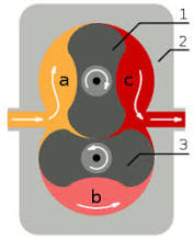
Refrigerant is pumped down before there is a major loss of refrigerant. Option 1: With Leak detector - the safest solution for small rooms & EN378 Leak detector directly connected to the indoor unit Pump down system directly connected to the main outdoor unit Pump down system activates when a leak is detected in the rooms & refrigerant collection will be immediate Due to exclusive Panasonic ECOi software the sensors communicate with the pump down system directly eliminating the need for an additional expensive communication network 1. Valves close / 2. Pump down system / 3. Room 1 / 6. Room 2 / 7. Option 2: Unique innovative algorithm to determine refrigerant leakage Panasonic has developed a new innovative algorithm which is able to detect leakage of R410A based on the following conditions: This solution is perfect for hotels, offices and public buildings where safety of the end users & building occupiers is paramount! It's also extremely cost effective as there is no need for expensive leakage sensor AND helps buildings qualify for additional BREEAM points

Apart from the fact customers have to comply with current EN378 2008 standards - where refrigeration concentration levels exceed practical safety limits of 0,44 kg/m³ - it’s a no brainer for customers where the safety of their staff & their occupants is essential and they want to protect their investment.
ac unit ge Other manufacturers can not compete on cost, quality or simplicity.
where is the air filter on my ac unitContact us for more information.
indoor ac unit cleaner This innovative pump down system can be connected in two ways: Without sensor leakage, using only the innovative algorithm Basic pump down function: Activate pump down process Collect the gas on the tank Close the valves to isolate the gas Save on operating costs

Refrigerant lines must be vacuumed after installing or reinstalling an A/C unit. Moisture inside refrigerant lines can contaminate the lines, causing your air conditioning unit to become sluggish. Anytime an A/C unit is installed, or reinstalled due to repair, the refrigerant lines must be vacuumed. Refrigerant already in the lines combines with the moisture that enters the lines. As soon as the A/C unit is turned on, the moisture begins to freeze, clogging the lines. This forces the A/C unit to work harder to cool the air in your home. Removing the moisture -- through use of a vacuum pump -- will allow your A/C unit to function effectively. Turn your A/C unit into the "Off" position. Remove the service valve caps, using a wrench. The two gold-colored valves are located on the refrigerant lines, where the lines enter the condensing unit. The valves are located toward the bottom of the back side of the A/C unit, or the side A/C unit that faces your home. Install the refrigerant manifold gauge hoses onto the service valve lines of the A/C unit.

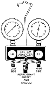
Thread each valve onto its respective hose by turning the valve in a clockwise motion, just as you would thread a watering hose onto an outside water spigot. The left hose of the gauge attaches to the larger, low-pressure line's service valve, while the right hose attaches to the smaller, high-pressure line's service valve. Check the sight glass on the vacuum pump to ensure it has enough oil. The oil level should be at the fill line located on the sight glass; some pumps will have an "Oil Level" line. If it is not, add more oil. The oil inside the vacuum pump does double duty, trapping contaminants from the A/C unit and keeping the pump from over heating while it is in use. Place the vacuum pump onto a flat surface next to the A/C unit. Thread the last -- and center -- hose from the refrigerant manifold gauge onto the intake valve of the vacuum pump. Thread it in a clockwise motion similar to Step 3. Switch the pump into the "On" position. Place both manifold gauge valves, located on either side of the manifold, into the "Open" position.

Air and moisture trapped in the A/C lines will now begin to exit through the vacuum pumps exhaust valve. Track the refrigerant manifold's left gauge readout, measured in inches of mercury, until the gauge reaches 29 inHg. Close each manifold valve and quickly shut off the vacuum pump. Wait 20 minutes, and then check to be sure the reading remains at 29 inHg. A reading other than 29 inHg, may mean a leak in the refrigerant system. Disconnect the refrigerant manifold gauge from the A/C unit and the vacuum pump from the refrigerant manifold gauge. Turn on your A/C unit to be sure it is working properly. Things You Will Need Wrench Vacuum pump and vacuum pump oil Refrigerant manifold gauge Tip References Robinair: AC Solutions/AC Vacuum Photo Credits Jupiterimages/liquidlibrary/Getty Images Suggest a CorrectionThe temperature of a refrigerated box can be controlled by a low-pressure control (LPC), instead of a thermostat, because of the pressure/temperature relationship in the refrigeration system.

By cycling the compressor in response to the suction (low side) pressure, box temperature can be controlled. This type of control is most popular in small-refrigerated boxes such as beer coolers. To control box temperature with a low-pressure control, the system must use a thermostatic expansion valve, non-bleed type. The condensing unit must be located in an ambient, which is warmer than the box’s highest operating temperature. As box temperature decreases, the evaporator temperature decreases, and a lower suction pressure results. When the suction pressure reaches the low-pressure control’s cut-out setting, the LPC’s contacts open and stop the compressor. As the box temperature rises, the evaporator’s temperature also rises, the evaporator pressure increases, and when the cut-in setting of the LPC is reached, its contacts close and the compressor is started. There are some advantages to this type of system. The low-pressure control will act as a “loss of charge” control.
Short cycling, due to door openings, etc., is prevented. The same is not true for a standard temperature control. Wiring is simplified and installed cost is reduced. Two settings need to be made on the LPC: The cut-in is the pressure that closes the LPC’s contacts and starts the compressor. This pressure relates to the refrigerated box’s highest temperature. As an example for a beer cooler: The desired box temperature is 36°F; the system is R-134A refrigerant. From a pressure/temperature chart, we see that 31.3 psig is 36°F for R-134A. This will be the cut-in setting. The differential is the difference between the cut-in and the cut-out pressures. The differential will determine the compressor “on” time: the time it takes to pull the suction pressure down to the cut-out setting. Usually it is advantageous to keep the compressor on as long as possible for maximum efficiency. 1. The box’s lowest temperature 2. The TD of the evaporator coil

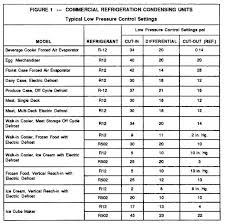
3. Desired compressor “on” time 4. The DP in the suction line between the evaporator and the LPC connection at the compressor. What all this means is that one picks cut-in and cut-out settings that should result in good temperature control, monitors the system, and then fine-tunes each specific job to achieve the desired results. shows the usual starting set points to set up a LPC for various applications. (R-134A can be substituted for R-12 and R-404A for R-502). Highest box temperature desired 36°F 36°F R-134A is 31 psig Set the cut-in at 31 psi 36°F minus 10°F is 26°F R-134A at 26°F is 23 psig Allow 2 - 3 psi for suction line DP 23 psig minus 3 psig = 20 psig 31 psia minus 20 psi = 11 psi Set the differential at 11 psi. The compressor will now go on at 33 psi and go off at 20-psi suction pressure. This should result in a box temperature of 34°F to 36°F. Depending on how well the system balance was made, that is, matching the evaporator to the compressor capacity at the selected suction temperature, the compressor run time will be long enough to give good efficiency and not short cycle.
If box temperature varies more than 2°or 3°F, or if the compressor short cycles, adjust the differential only, not the cut-in setting (raising the cut-in setting raises the box temperature)! Fine-tuning the differential setting should produce the desired results. The settings in Figure 1 are only a beginning reference. Variations in systems will probably require small corrections of the settings. Remember—too close a differential may maintain close temperature control, but cause short cycling, greatly shortening equipment life. A wide differential will give longer running time, but may cause wide temperature swings. The final chosen differential has to be a compromise. Probably the most common use of an LPC pump is in “pump down”. In a pump down system, a thermostat controls a solenoid valve in the liquid line. On a rise in temperature, the thermostat energizes the solenoid valve, allowing refrigerant to the TXV (pump-down systems must use TXV’s) into the evaporator and suction line.
The refrigerant pressure increases, causing the LPC to cut-in, starting the compressor. When the thermostat opens the circuit to the solenoid valve, the valve closes and the compressor pumps the refrigerant from the evaporator and suction line into the receiver and condenser, reducing the refrigerant pressure to the cut-out setting of the LPC and stops the compressor. If, during the off cycle, refrigerant leaks into the low side to raise the pressure to the LPC cut-in setting, the LPC will start the compressor for a short period until the pressure is lowered to the cut-out point and the compressor is once again stopped. These brief occasional cycles are not objectionable, but if they occur too often, are an indication of a leaky solenoid valve or leaky compressor valves. While pump-down is a low-cost, easy to install refrigeration control system, it is not necessary to wire from the refrigerated box to the compressor, the main benefit of a pump down system is the fact that the refrigerant is isolated in the condenser and receiver when the compressor is not running, preventing migration of refrigerant to the compressor’s crankcase.
The last place we want liquid refrigerant is in a compressor’s crankcase! The LPC cut-in setting should be selected first. For units located indoors, determine the lowest operating temperature of the unit. Subtract 3°to 5°F from this temperature. Using a T/P chart set the cut-in at that value. The cut-out setting should be a reasonable amount of PSI lower than the cut-in, but not so low that the compressor will have difficulty reaching the cut-out setting. Avoid cut-out settings that result in a vacuum. Even low temperature freezers using R-502 or R-404A should not be set lower than 0 psi cut-out. If the beer cooler, used as previous example, were to use a pump-down system, the LPC cut-in setting would be determined as follows: Lowest operating temperature of the unit 24°F (Lowest box temperature 34°F, 10°F coil TD equals 24°F) Subtract 3 to 5°F from 24°F. This results in 20°F. From a T/P chart, we see that R-134A at 20°F is about 18 psi.
Set the cut-in at 18 psi. A differential setting of 5 psi to 10 psi will result in a reasonable cut-out setting of 8 to 13 psi. For condensing units outdoors, either the coldest unit operating temperature or the coldest ambient temperature selects the cut-in setting, whichever is the lowest temperature. is a guide for setting the LPC for outdoor units. is typical of the piping for a pump-down system. Note that when the solenoid valve is closed (off) the refrigerant is essentially trapped between the solenoid valve and the discharge valves of the compressor. and Figure 6 show two of the more common wiring diagrams for pump-down systems. Another common use of LPC’s is to cycle condenser fans to maintain head pressure during cool weather conditions (note the word “cool”, not cold). Air-cooled condensers outdoors need head pressure control when required to operate in ambient temperatures below 60°F, for air conditioning, and below 50°F for refrigeration systems.
Fan cycling is only good to about 20°F above zero. Below that, flooded condenser valve systems should be used. An LP fan cycling control senses discharge (head) pressure and closes on rise of pressure. The control opens on a fall in head pressure and shuts off the condenser fan, or fans. Condensing temperatures range from 95°F to 105°F. The correct adjustment of the on/off control differential is important. Too small a differential will cause short cycling of the condenser fan and shorten the fan motor life. Too wide a differential will cause large fluctuations in head pressure and cause TXV hunting. A 35 to 50 psi differential is suggested, depending on usage. shows suggested pressure settings for a single fan condenser. is a chart for condensers with multiple fans. The pressure control for each fan should be set to cut-in about 10 psi apart. Very large condensers having four or more fans, usually have the fan cycling controls control two or more fans at a time.