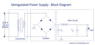
ac to dc power supply diagram

How Power Supplies Turn AC into DC in Electronic Circuits The task of turning alternating current into direct current is called rectification, and the electronic circuit that does the job is called a rectifier. The most common way to convert alternating current into direct current is to use one or more diodes, those handy electronic components that allow current to pass in one direction but not the other. Although a rectifier converts alternating current to direct current, the resulting direct current isn’t a steady voltage. It would be more accurate to refer to it as “pulsating DC.” Although the pulsating DC current always moves in the same direction, the voltage level has a distinct ripple to it, rising and falling a bit in sync with the waveform of the AC voltage that’s fed into the rectifier. For many DC circuits, a significant amount of ripple in the power supply can cause the circuit to malfunction. Therefore, additional filtering is required to “flatten” the pulsating DC that comes from a rectifier to eliminate the ripple.

There are three distinct types of rectifier circuits you can build: half-wave, full-wave, and bridge. The following describes each of these three rectifier types. The simplest type of rectifier is made from a single diode. This type of rectifier is called a half-wave rectifier because it passes just half of the AC input voltage to the output. When the AC voltage is positive on the cathode side of the diode, the diode allows the current to pass through to the output.
types of hvac careersBut when the AC current reverses direction and becomes negative on the cathode side of the diode, the diode blocks the current so that no voltage appears at the output.
is my ac unit under warranty Half-wave rectifiers are simple enough to build but aren’t very efficient.
cost of replacing a 5 ton ac unit
That’s because the entire negative cycle of the AC input is blocked by a half-wave rectifier. As a result, output voltage is zero half of the time. This causes the average voltage at the output to be half of the input voltage. Note the resistor marked RL. This resistor isn’t actually a part of the rectifier circuit. Instead, it represents the resistance imposed by the load that will ultimately be placed on the circuit when the power supply is put to use. A full-wave rectifier uses two diodes, which enables it to pass both the positive and the negative side of the alternating current input. The diodes are connected to the transformer. Notice that the full-wave rectifier requires that you use a center-tapped transformer. The diodes are connected to the two outer taps, and the center tap is used as a common ground for the rectified DC voltage. The full-wave rectifier converts both halves of the AC sine wave to positive-voltage direct current. The result is DC voltage that pulses at twice the frequency of the input AC voltage.

In other words, assuming the input is 60 Hz household current, the output will be DC pulsing at 120 Hz. The problem with a full-wave rectifier is that it requires a center-tapped transformer, so it produces DC that’s just half of the total output voltage of the transformer. A bridge rectifier overcomes this limitation by using four diodes instead of two. The diodes are arranged in a diamond pattern so that, on each half phase of the AC sine wave, two of the diodes pass the current to the positive and negative sides of the output, and the other two diodes block current. A bridge rectifier doesn’t require a center-tapped transformer. The output from a bridge rectifier is pulsed DC, just like the output from a full-wave rectifier. However, the full voltage of the transformer’s secondary coil is used. You can construct a bridge rectifier using four diodes, or you can use a bridge rectifier IC that contains the four diodes in the correct arrangement. A bridge rectifier IC has four pins: two for the AC input and two for the DC output.

Today, my son builds a simple 12V 2A DC power supply for a 12V solar pump. It is an Unregulated power supply because load is DC motor only.How to works I teach son to understand the working principle of this projects. The main principle, we use this project to reduce voltage from AC-line 220V to 12V DC.On Figure 1 The AC 220V 50HZ is connected to the circuit through S1- ON-OFF switch and F1-fuse to protect this circuit. Then they flows through a 2A transformer to reduce voltage into 12V AC. Next,through the both Diodes to rectifier AC to DC converter. Then,at a capacitor as filter to DC voltage. The LED1 is power on display and R1 limit current for LED use. Figure 1 the schematic diagram Parts you will needs T1____12V CT 12V, 2A transformer D1,D2____1N5402, 3A Diode C1_______2,200uF 25V Electrolytic capacitor R1_______1.2K 0.5W Resistors LED1_____LEDs as you like S1_______ON-OFF switches F1_______Fuse 1A Copper wires and nail 0.5inch, AC line powerHow to builds This projects myson do yourself a many steps.
Begin of all, put the paper on a sheet of plywood and Hammer a nail into the parts joint.He soldered all parts on nail head instead of the PCB.All parts at AC line is high voltage I connect them instead myson. Figure 2 Hammer a nail into the parts joint Figure 3 soldered all parts on nailWhen completed, He measure voltage at output is 17V No load (Figure 4) Figure 4 Then, he try to apply the DC pump as load. Then He measure current of load is about 0.9A as Figure 5 This project is applied at outdoor so he put it into the Plastic boxes to protect water as Figure 6This project of homeshooling boy is fist Electronic times we have happy it works great. Eleccircuit highly recommends EasyEDA for PCB design and order LM317 VARIABLE POWER SUPPLY A truly timeless circuit. LM317 is a versatile and highly efficient 1.2-37V voltage regulator that can provide up to 1.5A of current with a large heat sink. It's ideal for just about any application. Dual Polarity Power Supply

This dual polarity power supply is easy to build, requires few parts, and is adjustable from 0-15 volts. It is great for powering op amp circuits, as well as other circuits that require a dual... Fixed Voltage Power Supply The fixed voltage power supply is useful in applications where an adjustable output is not required. This supply is simple, but very flexable as the voltage it outputs is dependant only on the regulator and... High Current Power Supply High Current Power Supply [more] 0-50V 2A Bench power supply 0-50V 2A Bench power supply [more] 10 Amp 13.8 Volt Power Supply The circuit will give us 10 amps (12 amps surge) with performance that equals or exceeds any commercial unit. The circuit even has a current limiting feature which is a more reliable system than most... This supply uses no heavy step down transformer and has an extremely low parts count. The circuit can be built very small and can supply small currents for small projects.