ac to dc power supply circuit diagram

Posted by on Feb 13, 2013 in | This post has been written by Vishwam, an electronics geek and an awesome guitarist. He is a core member of roboVITics. Don’t forget to share your views once you read it! A power supply is a device which delivers an exact voltage to another device as per its needs. There are many power supplies available today in the market like regulated, unregulated, variable etc, and the decision to pick the correct one depends entirely on what device you are trying to operate with the power supply. Power supplies, often called power adapters, or simply adapters, are available in various voltages, with varying current capacities, which is nothing but the maximum capacity of a power supply to deliver current to a load (Load is the device you are trying to supply power to). One would ask himself, “Why do I make it myself, when it available in the market?” Well, the answer is- even if you buy one, it is bound to stop working in a while (and believe me, power supplies stop working without any prior indication, one day they’ll work, the next day they’ll just stop working!).

So, if you build one yourself, you will always know how to repair it, as you will know exactly what component/part of the circuit is doing what.
cheap used central air conditioning unitsAnd further, knowing how to build one, will allow you to repair the ones you have already bought, without wasting your money on a new one.
hunter ac unit Transformers are devices which step down a relatively higher AC input Voltage into a lower AC output voltage.
charging your ac unitTo find the input and output terminals of a transformer is very tricky. Refer to the following illustration or the internet to understand where what is. Basically, there are two sides in a transformer where the coil winding inside the transformer ends. Both ends have two wires each (unless you are using a center-tapped transformer for full wave rectification).

On the transformer, one side will have three terminals and the other will have two. The one with the three terminals is the stepped down output of the transformer, and the one with the two terminals is where the input voltage is to be provided. The 78XX series of voltage regulators is a widely used range of regulators all over the world. The XX denotes the voltage that the regulator will regulate as output, from the input voltage. For instance, 7805, will regulate the voltage to 5V. Similarly, 7812 will regulate the voltage to 12V. The thing to remember with these voltage regulators is that they need at least 2 volts more than their output voltage as input. For instance, 7805 will need at least 7V, and 7812, at least 14 volts as inputs. This excess voltage which needs to be given to voltage regulators is called Dropout Voltage. NOTE: The input pin is denoted as ‘1’, ground as ‘2’ and output as ‘3’. A bridge rectifier consists of an assembly of four ordinary diodes, by means of which we can convert AC Voltage into DC Voltage.

It is found to be the best model for AC to DC conversion, over Full wave and Half wave rectifiers. You can use any model you want, but I use this for the sake of high efficiency (If you are using the full wave rectifier model, you’ll need a center-tapped transformer, and you will only be able to use half of the transformed voltage). One thing to note about diodes is that they drop about 0.7V each when operated in forward bias. So, in bridge rectification we will drop 1.4V because at one instant two diodes are conducting and each will drop 0.7V. In case of Full wave rectifier, only 0.7V will be dropped. So how does this drop affect us? Well, this comes in handy while choosing the correct step down voltage for the transformer. See, our voltage regulator needs 2 Volts more than its output voltage. For the sake of explanation, let’s assume that we are making a 12V adapter. So the voltage regulator needs at least 14 Volts as input. So the output of the diodes (which goes into the voltage regulator) will have to be more than or equal to 14 Volts.

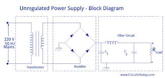
Now for the diodes’ input voltage. They’ll drop 1.4 Volts in total, so the input to them has to be greater than or equal to 14.0 + 1.4 = 15.4Volts. So I would probably use a 220 to 18 Volt step down transformer for that. So basically, the transformer step down voltage should be at least 3.4V more than the desired Power Supply output. We filter, both the input and output of the voltage regulator in order to get the smoothest DC Voltage as possible, from our adapter, for which we use capacitors. Capacitors are the simplest current filters available, they let AC current pass through and block DC, so they are used in parallel to the output. Furthermore, if there is a ripple in the input or output, a capacitor rectifies it by discharging the charge stored in it. Here is the circuit diagram for the Power Supply: The AC mains are fed to the transformer, which steps down the 230 Volts to the desired voltage. The bridge rectifier follows the transformer thus converting AC voltage into a DC output and through a filtering capacitor feeds it directly into the input (Pin 1) of the voltage regulator.

The common pin (Pin 2) of the voltage regulator is grounded. The output (Pin 3) of the voltage regulator is first filtered by a capacitor, and then the output is taken. Make the circuit on a general purpose PCB and use a 2 Pin (5A) plug to connect the transformer input to the AC mains via insulated copper wires. If you want to power up a device you bought from the market, you need to solder your Power supply output to an adapter jack. This adapter jack comes in a variety of shapes and sizes and completely depends on your device. I have included a picture of the most common type of adapter jack. If you want to power up a self made circuit or device, then you would probably run the output wires of your supply into your circuit directly. An important thing to note is that you will need to take care of the polarities, while using this supply, as most of the devices you will power up will only work on forward bias, and will not have an inbuilt rectifier to correct wrong polarities.
Almost all of the devices will need positive on the tip, and ground on the sleeve, except a few, for example, in the music industry, almost all the devices will need ground on the tip, and positive on the sleeve. You can add an LED with a current limiting resistor in series as indication of the power supply working. The resistance value is calculated as follows: Where, R is the series resistance value, and Vout is the output voltage of the voltage regulator (and the power supply as well). NOTE: The value of the resistor does not have to be exactly as calculated using this formula, it can be anything close to the calculated value, preferably greater. In addition to an LED, you can also add a switch to control the ON/OFF mode of the power supply. You can also use a Heat Sink, which is a metallic heat conductor attached to the voltage regulator with a bolt. It is used in case we need high current outputs from the power supply and the voltage regulator heats up.