types of ac transmission system

A flexible alternating current transmission system (FACTS) is a system composed of static equipment used for the AC transmission of electrical energy. It is meant to enhance controllability and increase power transfer capability of the network. It is generally a power electronics-based system. FACTS is defined by the IEEE as "a power electronic based system and other static equipment that provide control of one or more AC transmission system parameters to enhance controllability and increase power transfer capability." According to Siemens "FACTS Increase the reliability of AC grids and reduce power delivery costs. They improve transmission quality and efficiency of power transmission by supplying inductive or reactive power to the grid. Transmission on a no-loss line. In shunt compensation, power system is connected in shunt (parallel) with the FACTS. It works as a controllable current source. Shunt compensation is of two types: In the case of a no-loss line, voltage magnitude at the receiving end is the same as voltage magnitude at the sending end: Vs = Vr=V. Transmission results in a phase lag that depends on line reactance X.
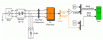
As it is a no-loss line, active power P is the same at any point of the line: Reactive power at sending end is the opposite of reactive power at receiving end: As is very small, active power mainly depends on whereas reactive power mainly depends on voltage magnitude. FACTS for series compensation modify line impedance: X is decreased so as to increase the transmittable active power. However, more reactive power must be provided. Reactive current is injected into the line to maintain voltage magnitude. Transmittable active power is increased but more reactive power is to be provided. Examples of FACTS for series compensation (schematic) Examples of FACTS for shunt compensation (schematic) ^ Proposed terms and definitions for flexible AC transmission system(FACTS), IEEE Transactions on Power Delivery, Volume 12, Issue 4, October 1997, pp. 1848–1853. ^ Flexible AC Transmission Systems (FACTS) - Siemens Narain G. Hingorani, Laszlo Gyugyi Understanding FACTS: Concepts and Technology of Flexible AC Transmission Systems, Wiley-IEEE Press, December 1999.
Xiao-Ping Zhang, Christian Rehtanz, Bikash Pal, Flexible AC Transmission Systems: Modelling and Control, Springer, March 2006. A. Edris, R. Adapa, M.H. Baker, L. Bohmann, K. Clark, K. Habashi, L. Gyugyi, J. Lemay, A. Mehraban, A.K. Myers, J. Reeve, F. Sener, D.R. Torgerson, R.R. Wood, Proposed Terms and Definitions for Flexible AC Transmission System (FACTS), IEEE Transactions on Power Delivery, Vol. 12, No. 4, October 1997. New ArticlesMOSFET as a SwitchRelationship of Line and Phase Voltages and Currents in a Star Connected System555 Timer and 555 Timer WorkingBistable MultivibratorMonostable MultivibratorAstable MultivibratorClosely Related ArticlesElectrical Power Transmission System and NetworkTransmission Line in Power SystemVoltage in Power Electric LinesShort Transmission LineMedium Transmission LineLong Transmission LinePerformance of Transmission LineABCD Parameters of Transmission LineSag in Overhead ConductorElectrical Power Cable Types of Overhead ConductorTesting of Electrical Power Cable |

Routine TestConductor Resistance Test of Electrical Power CablesTest for Thickness of Insulation of Power CableAnnealing Test for Wires and Conductors Tensile Test of ConductorsPersulphate Test of ConductorWrapping Test for ConductorsCapacitor Bank | Reactive Power CompensationTypes of Capacitor BankSpecifications or Rating of Power Capacitor BankShunt Capacitor Switchable Capacitor Bank or Switched Capacitor BankLocation of Shunt CapacitorsElectrical Insulator |
small window mounted ac unitsPorcelain Glass Polymer InsulatorTypes of Electrical Insulator |
central air conditioning units top ratedOverhead InsulatorInsulation Coordination in Power SystemElectrical Insulator Testing |
gas powered air conditioning unitsCause of Insulator failureElectrical Power Substation Engineering and LayoutElectrical Bus System and Electrical Substation LayoutMobile Substation |

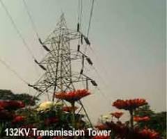
Mobile TransformerLoad Curve | Load Duration Curve | Daily Load CurveElectrical Transmission Tower Types and DesignMethods of Transmission Tower ErectionBasic Concept of Transmission Tower FoundationDesign of Foundations of Transmission Towers in different SoilsCorona Effect in Power SystemFerranti Effect in Power SystemAdvantages of Three Phase System over Single Phase SystemInductance in Single Conductor Power Transmission LineInductance in Three Phase Transmission LineWhy Supply Frequency 50 or 60 Hz not Other Values than these?Power System StabilityLoad Flow or Power Flow AnalysisTransient Stability in Power SystemFlexible AC Transmission Systems (FACTS)Tariff of electricity in IndiaPower Factor | Calculation and Power Factor ImprovementSkin Effect in Transmission LinesInductance of Two Wire Single Phase Transmission Line Electrical Power Transmission SystemElectrical power is generated at different generating stations. These generating stations are not necessarily situated at the load center.
During construction of generating station number of factors are to be considered from economical point of view. These all factors may not be easily available at load center; hence generating stations are not normally situated very nearer to load center. Load center is the place where maximum power is consumed. Hence there must be some means by which the generated power must be transmitted to the load center. Electrical transmission system is the means of transmitting power from generating station to different load centers. Factor to be Considered for Constructing a Generating Station During planning of construction of generating station the following factors to be considered for economical generation of electrical power. Easy availability of water for thermal power generating station. Easy availability of land for construction of power station including it's staff township. For hydro power station there must be a dam on river. So proper place on the river must be chosen in such a way that the construction of the dam can be done in most optimum way.

For thermal power station easy availability of fuel is one of the most important factors to be considered. Better communication for goods as well as employees of the power station also to be kept into consideration. For transporting very big spare parts of turbines, alternators etc, there must be wide road ways, train communication, and deep and wide river must pass away nearby the power station. For nuclear power plant, it must be situated in such a distance from common location so that there may be any effect from nuclear reaction the heath of common people. Many other factors are also to be considered, but there are beyond the scope of our discussion. All the factors listed above are very difficult to be available at load center. The power station or generating station must be situated where all the facilities are easily available. This place may not be necessarily at the load center. The power generated at generating station then transmitted to the load center by means of electrical power transmission system as we said earlier.

The power generated at generating station is in low voltage level as low voltage power generation has some economical values. Low voltage power generation is more economical than high voltage power generation. At low voltage level, both weight and insulation is less in the alternator, this directly reduces the cost and size of alternator. But this low voltage level power can not be transmitted directly to the consumer end as because this low voltage power transmission is not at all economical. Hence although low voltage power generation is economical but low voltage electrical power transmission is not economical. Electrical power is directly proportional to the product of electrical current and voltage of system. So for transmitting certain electrical power from one place to another, if the voltage of the power is increased then associated current of this power is reduced. Reduced current means less I2R loss in the system, less cross sectional area of the conductor means less capital involvement and decreased current causes improvement in voltage regulation of power transmission system and improved voltage regulation indicates quality power.

Because of these three reasons electrical power mainly transmitted at high voltage level. Again at distribution end for efficient distribution of the transmitted power, it is stepped down to its desired low voltage level. So it can be concluded that first the electrical power is generated at low voltage level then it stepped up to high voltage for efficient transmission of electrical energy. Lastly for distribution of electrical energy or power to different consumers it is stepped down to desired low voltage level. This brief discussion of electrical transmission system and network, but now we will discussed little bit more details about transmission of electrical energy. Transmission of Electrical Energy Fundamentally there are two systems by which electrical energy can be transmitted. High voltage DC electrical transmission system. High AC electrical transmission system. There are some advantages in using DC transmission system- Only two conductor are required for DC transmission system.
It is further possible to use only one conductor of DC transmission system if earth is utilized as return path of the system. The potential stress on the insulator of DC transmission system is about 70 % of same voltage AC transmission system. Hence, less insulation cost is involved in DC transmission system. Inductance, capacitance, phase displacement and surge problems can be eliminated in DC system. Even having these advantages in DC system, generally electrical energy is transmitted by three(3) phase AC transmission system. The alternating voltages can easily be stepped up and down, which is not possible in DC transmission system. Maintenance of AC substation is quite easy and economical compared to DC. The transforming of power in AC electrical sub station is much easier than motor-generator sets in DC system. But AC transmission system also has some disadvantages like, The volume of conductor used in AC system is much higher than that of DC.

The reactance of the line, affects the voltage regulation of electrical power transmission system. Problems of skin effects and proximity effects only found in AC system. AC transmission system is more likely to be affected by corona effect than DC system. Construction of AC electrical power transmission network is more completed than DC system. Proper synchronizing is required before inter connecting two or more transmission lines together, synchronizing can totally be omitted in DC transmission system. Transmission Line in Power SystemVoltage in Power Electric LinesABCD Parameters of Transmission LineTesting of Electrical Power Cable | Routine TestConductor Resistance Test of Electrical Power CablesTest for Thickness of Insulation of Power CableAnnealing Test for Wires and Conductors Capacitor Bank | Reactive Power CompensationSpecifications or Rating of Power Capacitor BankSwitchable Capacitor Bank or Switched Capacitor BankElectrical Insulator | Load Flow or Power Flow AnalysisTransient Stability in Power SystemFlexible AC Transmission Systems (FACTS)Tariff of electricity in IndiaPower Factor |