low power ac/dc converter
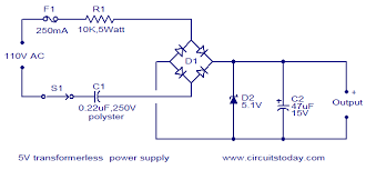
Is there any IC which converts 230V AC to 5V DC? As lossless as possible. I want to connect my microcontroller to an ordinary electrical socket and I don't have enough space available. voltage ac dc converter There's no such thing as "lossless" anything in electronics, and there's not a single IC that's designed to do what you want. But here are some different supply ideas. Since you didn't specify current consumption or efficiency, let's look at three different approaches: 5% efficiency or less Plug-in timers that are microcontroller-based usually use non-isolating power supplies, like this: R1 essentially drops the difference between the Zener diode and the AC mains potential, so it's not going to be efficient for anything except light loads. Also, your load can't change dramatically, as the resistor has to be sized to provide enough current to the zener to cause it to reverse avalanche, without providing too much current. If your load starts pulling too much current, its voltage will drop.

If your load doesn't pull enough current, the zener diode can be damaged. Excellent for extremely light loads (MCU + switch device) Load current isn't flexible; must be fixed within small window Mains-frequency regulated transformer supply You can always use a transformer (60:1 or so), a bridge rectifier, and a linear regulator, like this: This introduces a bulky, costly transformer into the design, but it's more efficient than the previous design, and your load can vary quite a bit. Designed for medium current loads -- a clock radio, for example. Fully-isolated Switch-mode AC/DC Converter Most efficient (and most complex) is a AC/DC switching converter. These work on the principle of first converting AC to DC, then switching the DC at very high frequencies to make optimal use of the transformer's characteristics, as well as minimize the size (and loss) of the filter network on the secondary. Power Integrations makes an IC that does all the control/feedback/driving -- all you need is to add a transformer and optoisolators.

Here's an example design: As you can see, AC mains voltage is immediately rectified and filtered to produce high voltage DC. The Power Integrations device switches this voltage rapidly across the transformer's primary side. High-frequency AC is seen on the secondary, and rectified and filtered. You'll notice that the component values are quite small, even considering the current use.
air conditioning fan on vs autoThis is because high-frequency AC requires much smaller components to filter than line-frequency AC.
heat pump unit outsideMost of these devices have special ultra-low-power modes that work quite well.
what is ac split unit These converters, in general, provide a great amount of efficiency and can also source high-power loads. These are the sorts of supplies you see in everything from tiny cell phone chargers to laptop and desktop computer power supplies.

High output current: can source 50+ amps of low voltage DC fairly easily. Large BOM (Bill of Materials) Requires thoughtful PCB layout Usually requires custom transformer design I know it's an old question, but you might want to see the SR086. At Vout you just need to use generic dc reg (e.g. 7805) to get your 5V. Note: This is not isolated, so it could be dangerous depending on the situation. I am mildly surprised that while the Non-Isolating Zener Supply was provided, there is no mention of a non-isolating capacitive reactance circuit voltage divider. If the device functions within a narrow current requirement, this can be reasonably efficient. The chief issue with the design (well, besides not providing mains isolation) is that you cannot use electrolytic caps (which are polarized), and thus must source uF-range film caps rated at the AC RMS voltage (so a 240V circuit would need caps rated at 350V or higher), which are not especially compact.

The capacitance values are also dependent upon AC mains frequency (60Hz in the USA, 50Hz in much of the rest of the world), as well as the actual mains voltage (which will be the case with any non-switching design). IMO, a MOV (metal-oxide varistor) should be added to all of these designs to protect against line transients. One is present in the SR086 schematic (which curiously doesn't show attribution). That should bridge Line-to-Neutral (for US 120V mains), or Line-to-Line (for 240V mains), and be tapped between the fuse and load (as seen in the SR086 schematic), and ideally before any switches (since a sufficiently high spike can bridge a switch). This will help to protect your circuit - a MOV should handle many small spikes and surges with no problem, and will give its life on the big spike which would otherwise fry everything in your circuit, while the fuse between the MOV and mains will blow if the MOV shorts while doing its job. I don't have a ready-made schematic of a capacitive reactance voltage divider, but you can find one in the Wikipedia article for Voltage Dividers

Wikipedia article for Capacitive Power Supply. The basic premise is that since you're dealing with AC, the capacitive reactance mimics resistance, but with the benefit of not actually "burning off" the energy - it is stored in the cap and returned to the line on the negative AC cycle. Old but actual question. After evaluating tens of approaches for AC/DC power converters I concluded following (for myself). Small size as possible. Less components as possible (footprint, size, price). Less heat dissipation (efficiency in other words). Low current, very low voltage, low output power. Isolation: in my application it's well isolated by box, no human protection needed. (So far, I am going with LDO regulator LR8 based PSU. Best solution for current up to 30mA. Can be connected in parallel to get 100mA for extra price and footprint.) UPDATE: The LR8-based PSU is not relevant, its practical current is 3mA only. I implemented pretty small, simple and stable PSU with LNK305 IC.

When R1=2k the output voltage is about 3.3V. C2 better to use few hundreds uF. All input circuit (D3, D4, L2, C4) I replaced with diode bridge. C5=2.2uF is enough - for small size and cost. These circuits are so far good enough (taken from the Internet): less components + isolation bonus. This is second best non-isolated very simple circuit by ST. In both circuits above the coil or transformer are pretty big and expensive. All above in this thread due to complexity, transformers, isolation, total PSU price, etc. Viper17 and Altair04 due to complexity and transformer. HV-2405E based due to end of life. It's not actually an "IC" but it's a PCB mount package. Or if you don't need 5W, this one is only 1W Building on top of the 7805 idea, by using parts with less loss. simulate this circuit – Schematic created using CircuitLab This circuit replaced all 1N4001 rectifiers with 1N5819 Schottky rectifiers and used a low dropout linear regulator AMS1117-5.0.