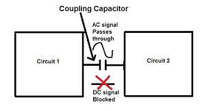
capacitor in a ac circuit
AC Applications of the Wheatstone Bridge When we applied a dc voltage to a resistor and capacitor in series, the capacitor charged to the applied voltage along an exponential curve, and then just sat there. This is not the case when an ac voltage is applied to this combination as shown in the schematic diagram to the right. input voltage is constantly changing, so the capacitor will constantly charge and discharge as it continually tries to oppose the changes. Essentially, R and C in this circuit now form a voltage divider for ac. We can expect that part of the applied voltage will appear across R, and part will appear across C. But how much voltage will appear across each As a practical example of such a circuit, assume VAC = 10 vrms at a frequency of 1 kHz. C = 0.01 µf and R = 15K. If we were to build this circuit with an accurate audio frequency generator, we would measure a voltage of 6.855 vrms across the resistor, and 7.275 vrms across

This of course adds up to considerably more than the 10 vrms supplied by the generator. How is this possible? The question is compounded by the fact that C will cause a phase shift between voltage and current. Since this is a series circuit, the current must necessarily be the same everywhere in the circuit. voltage across the capacitor will lag that current by 90°, while at
ac motor control board the same time the voltage across the resistor will be in phase with the
ac unit vibrationHow can we deal with such a mess?
outside ac unit iced over The real problem here is that 90° phase shift between vCSince they are not in phase and some voltage is dropped across each component, the phase relationship between generator voltage

and generator current must be somewhere between the two extremes. to be able to determine that relationship, as well as to determine the combined effect of R and XC in this circuit. One solution is to map the component voltages graphically, as shown toUsing X-Y coordinate axes, the positive X axis is defined as the zero-degree reference, and counter-clockwise rotation is defined as the direction of increasing positive angles. Since the circuit current is necessarily the same throughout the circuit, it is used as the reference phase angle. vR, is in phase with the current as shown in red. voltage, vC, is at -90° as shown in blue. In this way, we can represent the voltages across R and C as vectors, having direction asNow it is clear that the composite voltage comprising both vR and vC must be the vector sum of the two, as To find the composite voltage, we must apply the formula for the diagonal of a rectangle, and find the square root of the sum of the
Since our generator produces an output of 10 vrms, this confirms our Another point to consider here is that this circuit contains both resistance (R) and reactance (XC). This is neither a pure resistance or a pure reactance. We need a name for this combined characteristic, and a means of calculating it. The name is easy enough; the combined characteristic is named impedance, and is represented by the letter Z. To calculate Z, we must first note that, in accordance with Ohm's Law, R = vR/I andBut we already know that the voltages are 90° out of phase. Since the circuit current, i, is the same everywhere, then R and XC must be 90° out of phase asThus, we must apply the same method for finding Z as we did for finding the composite voltage. The full set of calculations for this circuit, then, using the circuit values given above, is: The actual phase angle between generator current and generator voltage is (with voltage lagging current):

Thus, all circuit values and calculations remain consistent with each other and with actual measurements made on experimental circuits. If we have a circuit involving multiple capacitors and resistors, it becomes necessary to deal with resistance and reactance in a moreFor example, consider the circuit to the right. R3 and C3 are in series, but that combination is in parallel with R2. parallel combination is then in series with C2, and then the sequence repeats with R1 and C1. We can calculate the impedance of R3 and C3, but then trying to combine that with R2 becomes very complicated. complications only increase as we include more components. instead is a way to deal with both reactive and resistive components so that we can keep them separate but still use them together. there is a way to do just that. The basic requirement is that we separate the reactive components and mark their values in such a way as to clearly indicate the appropriate

We can do this by introducing a new mathematical operator, j, which will represent that rotation. indicates rotation by -90°. Rotation by 180° is indicated by j × j or j². Since this is a multiplying factor, it is also true that j² = -1. If you've ever worked with "imaginary numbers," this concept will be familiar to you. However, in electronics the lower-case letter "i" is used to designate signal current, so we use "j" in this role In this context, the impedance of our original example circuit for this page would be written as 15K - j15.92K. Numbers written in this format are known as complex numbers. calculations are performed using complex numbers, and the final conversion to determine Z as a single impedance value is performed only as the final step, or sometimes not at all. Especially note the "-" sign associated with XC. If we write the expression in its most basic form, it becomes: Of course, 1/ωC = XC.