capacitor for ac current

Capacitors do not behave the same as resistors. Whereas resistors allow a flow of electrons through them directly proportional to the voltage drop, capacitors oppose changes in voltage by drawing or supplying current as they charge or discharge to the new voltage level. The flow of electrons “through” a capacitor is directly proportional to the rate of change of voltage across the capacitor. This opposition to voltage change is another form of reactance, but one that is precisely opposite to the kind exhibited by inductors. Expressed mathematically, the relationship between the current “through” the capacitor and rate of voltage change across the capacitor is as such: The expression de/dt is one from calculus, meaning the rate of change of instantaneous voltage (e) over time, in volts per second. The capacitance (C) is in Farads, and the instantaneous current (i), of course, is in amps. Sometimes you will find the rate of instantaneous voltage change over time expressed as dv/dt instead of de/dt: using the lower-case letter “v” instead or “e” to represent voltage, but it means the exact same thing.

To show what happens with alternating current, let’s analyze a simple capacitor circuit: (Figure below) Pure capacitive circuit: capacitor voltage lags capacitor current by 90o
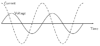
best buy wall ac units If we were to plot the current and voltage for this very simple circuit, it would look something like this: (Figure below)
low profile roof top ac unit Pure capacitive circuit waveforms.
different types of flexible ac transmission system Remember, the current through a capacitor is a reaction against the change in voltage across it. Therefore, the instantaneous current is zero whenever the instantaneous voltage is at a peak (zero change, or level slope, on the voltage sine wave), and the instantaneous current is at a peak wherever the instantaneous voltage is at maximum change (the points of steepest slope on the voltage wave, where it crosses the zero line).
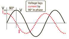
This results in a voltage wave that is -90o out of phase with the current wave. Looking at the graph, the current wave seems to have a “head start” on the voltage wave; the current “leads” the voltage, and the voltage “lags” behind the current. Voltage lags current by 90o in a pure capacitive circuit. As you might have guessed, the same unusual power wave that we saw with the simple inductor circuit is present in the simple capacitor circuit, too: (Figure below) In a pure capacitive circuit, the instantaneous power may be positive or negative. As with the simple inductor circuit, the 90 degree phase shift between voltage and current results in a power wave that alternates equally between positive and negative. This means that a capacitor does not dissipate power as it reacts against changes in voltage; it merely absorbs and releases power, alternately. A capacitor’s opposition to change in voltage translates to an opposition to alternating voltage in general, which is by definition always changing in instantaneous magnitude and direction.
For any given magnitude of AC voltage at a given frequency, a capacitor of given size will “conduct” a certain magnitude of AC current. Just as the current through a resistor is a function of the voltage across the resistor and the resistance offered by the resistor, the AC current through a capacitor is a function of the AC voltage across it, and the reactance offered by the capacitor. As with inductors, the reactance of a capacitor is expressed in ohms and symbolized by the letter X (or XC to be more specific). Since capacitors “conduct” current in proportion to the rate of voltage change, they will pass more current for faster-changing voltages (as they charge and discharge to the same voltage peaks in less time), and less current for slower-changing voltages. What this means is that reactance in ohms for any capacitor is inversely proportional to the frequency of the alternating current. Reactance of a 100 uF capacitor: Please note that the relationship of capacitive reactance to frequency is exactly opposite from that of inductive reactance.

Capacitive reactance (in ohms) decreases with increasing AC frequency. Conversely, inductive reactance (in ohms) increases with increasing AC frequency. Inductors oppose faster changing currents by producing greater voltage drops; capacitors oppose faster changing voltage drops by allowing greater currents. As with inductors, the reactance equation’s 2πf term may be replaced by the lower-case Greek letter Omega (ω), which is referred to as the angular velocity of the AC circuit. Thus, the equation XC = 1/(2πfC) could also be written as XC = 1/(ωC), with ω cast in units of radians per second. Alternating current in a simple capacitive circuit is equal to the voltage (in volts) divided by the capacitive reactance (in ohms), just as either alternating or direct current in a simple resistive circuit is equal to the voltage (in volts) divided by the resistance (in ohms). The following circuit illustrates this mathematical relationship by example: (Figure below) However, we need to keep in mind that voltage and current are not in phase here.

As was shown earlier, the current has a phase shift of +90o with respect to the voltage. If we represent these phase angles of voltage and current mathematically, we can calculate the phase angle of the capacitor’s reactive opposition to current. Voltage lags current by 90o in a capacitor. Mathematically, we say that the phase angle of a capacitor’s opposition to current is -90o, meaning that a capacitor’s opposition to current is a negative imaginary quantity. This phase angle of reactive opposition to current becomes critically important in circuit analysis, especially for complex AC circuits where reactance and resistance interact. It will prove beneficial to represent any component’s opposition to current in terms of complex numbers, and not just scalar quantities of resistance and reactance.During this charging process, a charging current, ( i ) will flow into the capacitor opposing any changes to the voltage at a rate that is equal to the rate of change of the electrical charge on the plates.

This charging current can be defined as: i = CdV/dt. Once the capacitor is “fully-charged” the capacitor blocks the flow of any more electrons onto its plates as they have become saturated. However, if we apply an alternating current or AC supply, the capacitor will alternately charge and discharge at a rate determined by the frequency of the supply. Then the Capacitance in AC circuits varies with frequency as the capacitor is being constantly charged and discharged. We know that the flow of electrons onto the plates of a capacitor is directly proportional to the rate of change of the voltage across those plates. Then, we can see that capacitors in AC circuits like to pass current when the voltage across its plates is constantly changing with respect to time such as in AC signals, but it does not like to pass current when the applied voltage is of a constant value such as in DC signals. Consider the circuit below. In the purely capacitive circuit above, the capacitor is connected directly across the AC supply voltage.

As the supply voltage increases and decreases, the capacitor charges and discharges with respect to this change. We know that the charging current is directly proportional to the rate of change of the voltage across the plates with this rate of change at its greatest as the supply voltage crosses over from its positive half cycle to its negative half cycle or vice versa at points, 0o and 180o along the sine wave. Consequently, the least voltage change occurs when the AC sine wave crosses over at its maximum or minimum peak voltage level, ( Vm ). At these positions in the cycle the maximum or minimum currents are flowing through the capacitor circuit and this is shown below. At 0o the rate of change of the supply voltage is increasing in a positive direction resulting in a maximum charging current at that instant in time. As the applied voltage reaches its maximum peak value at 90o for a very brief instant in time the supply voltage is neither increasing or decreasing so there is no current flowing through the circuit.

As the applied voltage begins to decrease to zero at 180o, the slope of the voltage is negative so the capacitor discharges in the negative direction. At the 180o point along the line the rate of change of the voltage is at its maximum again so maximum current flows at that instant and so on. Then we can say that for capacitors in AC circuits the instantaneous current is at its minimum or zero whenever the applied voltage is at its maximum and likewise the instantaneous value of the current is at its maximum or peak value when the applied voltage is at its minimum or zero. From the waveform above, we can see that the current is leading the voltage by 1/4 cycle or 90o as shown by the vector diagram. Then we can say that in a purely capacitive circuit the alternating voltage lags the current by 90o. We know that the current flowing through the capacitance in AC circuits is in opposition to the rate of change of the applied voltage but just like resistors, capacitors also offer some form of resistance against the flow of current through the circuit, but with capacitors in AC circuits this AC resistance is known as Reactance or more commonly in capacitor circuits

, Capacitive Reactance, so capacitance in AC circuits suffers from Capacitive Reactance. Capacitive Reactance in a purely capacitive circuit is the opposition to current flow in AC circuits only. Like resistance, reactance is also measured in Ohm’s but is given the symbol X to distinguish it from a purely resistive value. As reactance is a quantity that can also be applied to Inductors as well as Capacitors, when used with capacitors it is more commonly known as Capacitive Reactance. For capacitors in AC circuits, capacitive reactance is given the symbol Xc. Then we can actually say that Capacitive Reactance is a capacitors resistive value that varies with frequency. Also, capacitive reactance depends on the capacitance of the capacitor in Farads as well as the frequency of the AC waveform and the formula used to define capacitive reactance is given as: F is in Hertz and C is in Farads. 2πF can also be expressed collectively as the Greek letter Omega, ω to denote an angular frequency.

From the capacitive reactance formula above, it can be seen that if either of the Frequency or Capacitance where to be increased the overall capacitive reactance would decrease. As the frequency approaches infinity the capacitors reactance would reduce to zero acting like a perfect conductor. However, as the frequency approaches zero or DC, the capacitors reactance would increase up to infinity, acting like a very large resistance. This means then that capacitive reactance is “Inversely proportional” to frequency for any given value of Capacitance and this shown below: The capacitive reactance of the capacitor decreases as the frequency across it increases therefore capacitive reactance is inversely proportional to frequency. The opposition to current flow, the electrostatic charge on the plates (its AC capacitance value) remains constant as it becomes easier for the capacitor to fully absorb the change in charge on its plates during each half cycle. Also as the frequency increases the current flowing through the capacitor increases in value because the rate of voltage change across its plates increases.

Then we can see that at DC a capacitor has infinite reactance (open-circuit), at very high frequencies a capacitor has zero reactance (short-circuit). Find the rms current flowing in an AC capacitive circuit when a 4uF capacitor is connected across a 880V, 60Hz supply. In AC circuits, the sinusoidal current through a capacitor, which leads the voltage by 90o, varies with frequency as the capacitor is being constantly charged and discharged by the applied voltage. The AC impedance of a capacitor is known as Reactance and as we are dealing with capacitor circuits, more commonly called Capacitive Reactance, XC When a parallel plate capacitor was connected to a 60Hz AC supply, it was found to have a reactance of 390 ohms. Calculate the value of the capacitor in micro-farads. This capacitive reactance is inversely proportional to frequency and produces the opposition to current flow around a capacitive AC circuit as we looked at in the AC Capacitance tutorial in the AC Theory section.