air handling unit location building
Air Handling Unit (AHU) An Air Handling Unit (AHU) is used to re-condition and circulate air as part of a heating, ventilating and air-conditioning system.An Air Handling Unit (AHU) is used to re-condition and circulate air as part of a heating, ventilating and air-conditioning system.The basic function of the AHU is take in outside air, re-condition it and supply it as fresh air to a building. All exhaust air is removed, which creates an acceptable indoor air quality. Depending on the required temperature of the re-conditioned air, the fresh air is either heated by a recovery unit or heating coil, or cooled by a cooling coil.In buildings, where the hygienic requirements for air quality are lower, some of the air from the rooms can be re-circulated via a mixing chamber and this can result in significant energy savings. A mixing chamber has dampers for controlling the ratio between the return, outside and exhaust air. The AHU is a large metal box containing separate ventilators for supply and exhaust, heating coil, cooling coil, heating/cooling recovery system, air filter racks or chambers, sound attenuators, mixing chamber, and dampers.

AHUs connect to ductwork that distributes the conditioned air through the building, and returns it to the AHU.A heat/cooling recovery exchanger is normally fitted to the AHU for energy savings and increasing capacity.An AHU designed for outdoor use, typically on roofs, is also known as a rooftop unit (RTU). Some text in the modal.The Conditioned Air Module (CAM) unit is a modular zonal air handling unit which takes in air from the floor void and returns it to the space fully treated and conditioned.
no heat from my ac unitIt’s compact design allows it to be located free standing within the working environment, or placed within cupboard space, corridors or in a small plant room
ac unit fan not starting With the Flexible Space System, the building is divided up into several zones per floor, divided into supply and return channels using air segregation baffle.
2 ton package ac unit
Each CAM unit serves one zone, of between 100 – 300 m², and the conditioned air is distributed to the workspace via the low pressure plenum and into the space using fan terminal units CAM-C sizes: CAM C-15 / CAM C-25 / CAM C-35 The CAM-C unit with underfloor supply and underfloor return is the most flexible option allowing total elimination of ceiling based duct work, enabling reduced slab to slab height, enhanced ventilation and comfort CAM-V sizes: CAM-V11 / CAM-V22 / CAM-V33 / CAM-V44 The CAM-V unit with underfloor supply and ceiling or high level return allows the return air to be drawn out through the false ceiling with no requirement for underfloor baffle, allowing use of the larger surface of floor slab to distribute the supply air, increasing the effect of thermal mass storage CAM-C baseframe options are available to divide supply and return air channels and to accommodate different airflow patterns for any architectural or building design layout need

The CAM-V baseframe is located within the raised floor, and has no provision for direct connection to ducting or piping. Piping is assumed to be routed through the front opening of the baseframe Each CAM is supplied with a complete internal wiring loom connecting all fitted electrical elements. A gland is provided for the incoming power and control wiring. A factory-wired terminal board is isolated from the airflow, and includes an internal isolator for the complete isolation of the unit during maintenance Supply and return sensors are supplied with the units along with a length of two core control cable. Automatic control of the unit is enabled via the Flexface board. Visualisation of the controls is through a Flexmatic display unit providing easy access to set point adjustment and other functions Hard-wired connections for remote starting/stopping plus common alarm signals are standard features of all CAM’s, but comprehensive communication with most Building Management Systems (BMS) can be achieved using a Flexgateway module

Air Handling Unit Transmitters Project Lead: Karen Lobo Sponsor: Physical Plant-Campus Services Project Theme: Energy Conservation & Efficiency Project Description: Install MS Magnesense Differential Pressure Transmitters on air handling units in eight campus buildings. These switches will notify PP-CS’s Energy Management System when filters are reaching the end of their life cycles and need to be replaced. Using the switches will end the current method of relying on scheduled replacement dates and human observation, which are often incorrect and lead to the replacement of filters that still have lifecycle remaining. Goals: Order and install new air filters only when EMS has been notified by the MS Magnesense Differential Pressure Transmitters. This project hopes to realize the extended life cycle of air filters for a time space of 50% greater than the current method. Savings include energy, human labor, purchase and transportation of new filters, and disposal and transportation of old filters.
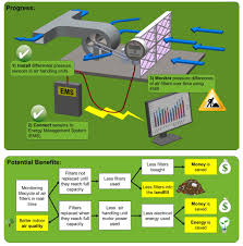
Furthermore, data loggers installed at each location will measure Amp and voltage needed to calculate energy consumption and monitor decreased usage. This project will also help with LEED credit application and compliance with CalGreen code for indoor air quality. TGIF Blog Posts about Air Handling Unit Transmitters Project was delayed due to difficulty hiring a student intern and the project received TGIF approval for a timeline adjustment. Purchased the project equipment: 6 Differential Pressure Switches Data Loggers Filters and Conduit. 2 installed at California Hall. 3M vs. Filtrite (both mini pleated filters). Testing two different types of filters against each other to see which one has the longest life cycle - new filters will reduce labor costs, landfill waste, vehicle gas for traveling to the location. Using the Energy Management System to monitor pressure drop on filters on a monthly basis. 2 installed at Koshland Hall. Mini pleated vs. bag/ring combo filters.

Hired student intern Ace Haidrey. Stationary engineer Mike Schefers will work with Ace on the project; Mike will provide Ace with education, advising, and mentorship on energy and HVAC. Next Steps: Project will focus on installations at Bechtel Hall, as well as the on-going monitoring of the equipment results. Met with filter vendors and evaluated filters for the test sites. Walked Bechtel Hall to prep the site for installing the Differential Pressure Switches. 2 installed at Bechtel Hall. Filtrair vs Tridem filters. 1 installed at Barker Hall. Working to see if collaboration with Zero Waste Research Center is possible. Researching companies who will pick up used air filters for recycle. Future Plans: The project hopes to continue in the next academic school year, 2013-2014. The next steps for this project include the accrual of data in the next year for each of the buildings and to continue to monitor them throughout the year. Data to be collected: