ac to dc power supply definition

Ever heard of the iconic metal band AC/DC? Do you know what the name stands for? It may sound a bit weird, but it actually stands for the electric currents AC (Alternating current) and DC (Direct current). The idea of the name comes from the initials ‘AC/DC’ on a sewing machine. So, what is AC/DC, and why is it important to know the difference? Contents1 Definitions2 AC Power vs DC Power3 Comparison Chart4 Video AC Power – Known as Alternating current, the AC is an electric current with electric charges that flows in reverse direction periodically. It is the most common and most preferred electric power delivered to businesses and residences. This is because the voltage can be changed through a transformer to comply with the transmission. It was first tested with a dynamo electric generator that was based on Michael Faraday’s Principles and constructed by Hippolyte Pixxi in 1832. AC power can be identified through the wave form sine wave or sinusoid (a mathematical curve that describes repetitive oscillation, or in simpler terms, curved lines) used as a label.

This represents the electric cycle and is measured according to its cycles per second, so each time a current travels in one direction, back to itself, it is considered one complete cycle. This gives you the unit measurement ‘Hertz or Hz’. Taking the typical frequency used in Europe which is 50 Hz that translates into 60 cycles per second. Note: AC is usually found in homes and industry with powers of 120 volts to 240 volts. DC Power – Known as Direct current (Previously galvanic current), DC is an electric current with electric charges that flows in a single direction. Because of this, it is easier to understand the electrical flow due to its constant voltage/current. It is usually used to charge batteries and as a power supply for electrical devices. Looking back at our history, you have probably already heard of the name Thomas Edison, who introduced the first investor-owned electric utility in 1882, and made the first commercial electric power transmission in the mid 1950’s.

DC power can be identified through a combined plus and minus sign, a straight line/s, or a dotted line. Unlike AC power, DC power won’t cycle back to where it started from, thus the frequency of its electric cycle is invalid or zero.
air conditioning units for restaurant Note: DC is usually found stored in batteries that can reach up to 12 volts (due to the wide availability of 12-volt equipment).
home ac repair do it yourself What’s the difference between AC power and DC power?
how much are 3 ton ac unitsWhile it is technically hard to understand, with a few examples, you’ll at least have an idea of which is which, and what’s what. If you’re reading this, chances are you’re using a laptop, a desktop, or a mobile device.
If you do use a laptop, then it’s safe to say that you are using both AC and DC power, and here’s the simple explanation. The nozzle or plug that connects your laptop to an outlet is using AC current, but when the current does reach your laptop, the power adapter then transforms the AC into DC. Same goes for your mobile devices. Desktop computers on the other hand have power supplies that can accommodate an AC current, a DC one, or even both. It really depends on what power supply you are using. To summarize, AC has an alternating current of 50 Hz or 60 Hz (depending on location), while DC has none. The flow of an AC current is reversible, while DC can only flow in one direction. AC is able to transfer current over long distances and provide more energy, while DC can only transfer limited energy. And finally, AC power is preferred in homes and industries, while DC is more preferred on electrical devices that are powered by fuel cells, batteries, and generators. Note: AC/DC refers to a device that can run on either type of current

You can check out the video below to know more about AC and DC.New ArticlesMOSFET as a SwitchRelationship of Line and Phase Voltages and Currents in a Star Connected System555 Timer and 555 Timer WorkingBistable MultivibratorMonostable MultivibratorAstable MultivibratorClosely Related ArticlesOp-amp | Working Principle of Op-ampAmplifier Gain | Decibel or dB GainIntegrated Circuits | Types of ICRegulated Power SupplyLaser | Types and Components of LaserWork FunctionInverting AmplifierMobility of Charge CarrierWhat are Photo Electrons? Electron volt or eVEnergy Quanta | Development of Quantum Physics Wave Particle Duality PrincipleHeisenberg Uncertainty PrincipleSchrodinger Wave Equation and Wave FunctionCyclotron Basic Construction and Working PrincipleDiode | Working Principle and Types of DiodeDiode CharacteristicsWhat is Zener Diode?Application of Zener DiodeVacuum Diode History Working Principle and Types of Vacuum Diodep-n Junction Diode and Characteristics of p-n JunctionFull Wave Diode RectifierHalf Wave Diode RectifierP-I-N Photodiode |

Avalanche Photo DiodeLED or Light Emitting DiodeTunnel Diode and its ApplicationsGUNN DiodeVaractor DiodeLaser DiodeFull Wave RectifiersBridge RectifiersMOSFET | Working Principle of p-channel n-channel MOSFETMOSFET CircuitsMOS Capacitor | MOS Capacitance C V CurveApplications of MOSFETMOSFET as a SwitchDiode Bridge RectifierTheory of SemiconductorIntrinsic SemiconductorExtrinsic SemiconductorsEnergy Bands of SiliconDonor and Acceptor Impurities in Semiconductor Conductivity of SemiconductorCurrent Density in Metal and Semiconductor Intrinsic Silicon and Extrinsic SiliconP Type SemiconductorN Type SemiconductorP N Junction Theory Behind P N JunctionForward and Reverse Bias of P N JunctionZener BreakdownAvalanche BreakdownHall Effect Applications of Hall EffectBipolar Junction Transistor or BJT | N-P-N or P-N-P Transistor Application Theory Biasing AmplifierApplications of Bipolar Junction Transistor or BJT | History of BJTBiasing of Bipolar Junction Transistor | BJT or Bipolar Transistor BiasingJFET or Junction Field Effect TransistorQuestions on JFET or Junction Field Effect TransistorDIAC Construction Operation and Applications of DIACTRIACTransistor as SwitchApplication of Field Effect TransistorTypes of TransistorsTransistor CharacteristicsTransistor BiasingPhototransistorn-channel JFET and p-channel JFET
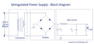
Today almost every electronic device needs a dc supply for its smooth operation and they need to be operated within certain power supply limits. This required dc voltage or DC supply is derived from single phase ac mains.A regulated power supply can convert unregulated an ac (alternating current or voltage) to a constant dc (direct current or voltage). A regulated power supply is used to ensure that the output remains constant even if the input changes. A regulated DC power supply is also called as a linear power supply, it is an embedded circuit and consists of various blocks. The regulated power supply will accept an ac input and give a constant dc output. Figure below shows the block diagram of a typical regulated dc power supply. The basic building blocks of a regulated dc power supply are as follows: A step down transformer Operation of Regulated Power Supply A step down transformer will step down the voltage from the ac mains to the required voltage level.

The turn’s ratio of the transformer is so adjusted such as to obtain the required voltage value. The output of the transformer is given as an input to the rectifier circuit. Rectifier is an electronic circuit consisting of diodes which carries out the rectification process. Rectification is the process of converting an alternating voltage or current into corresponding direct (DC) quantity. The input to a rectifier is ac whereas its output is unidirectional pulsating dc. Usually a full wave rectifier or a bridge rectifier is used to rectify both the half cycles of the ac supply (full wave rectification). Figure below shows a full wave bridge rectifier. A bridge rectifier consists of four p-n junction diodes connected in the above shown manner. In the positive half cycle of the supply the voltage induced across the secondary of the electrical transformer i.e. VMN is positive. Therefore point E is positive with respect to F. Hence, diodes D3 and D2 are reversed biased and diodes D1 and D4 are forward biased.

The diode D3 and D2 will act as open switches (practically there is some voltage drop) and diodes D1 andD4 will act as closed switches and will start conducting. Hence a rectified waveform appears at the output of the rectifier as shown in the first figure. When voltage induced in secondary i.e. VMN is negative than D3 and D2 are forward biased with the other two reversed biased and a positive voltage appears at the input of the filter. The rectified voltage from the rectifier is a pulsating DC voltage having very high ripple content. But this is not we want, we want a pure ripple free dc waveform. Hence a filter is used. Different types of filters are used such as capacitor filter, LC filter, Choke input filter, π type filter. Figure below shows a capacitor filter connected along the output of the rectifier and the resultant output waveform. As the instantaneous voltage starts increasing the capacitor charges, it charges till the waveform reaches its peak value. When the instantaneous value starts reducing the capacitor starts discharging exponentially and slowly through the load (input of the regulator in this case).
Hence, an almost constant dc value having very less ripple content is obtained. This is the last block in a regulated DC power supply. The output voltage or current will change or fluctuate when there is change in the input from ac mains or due to change in load current at the output of the regulated power supply or due to other factors like temperature changes. This problem can be eliminated by using a regulator. A regulator will maintain the output constant even when changes at the input or any other changes occur. Transistor series regulator, Fixed and variable IC regulators or a zener diode operated in the zener region can be used depending on their applications. IC’s like 78XX and 79XX are used to obtained fixed values of voltages at the output. With IC’s like LM 317 and 723 etc we can adjust the output voltage to a required constant value. Figure below shows the LM317 voltage regulator. The output voltage can be adjusted with adjusting the values of resistances R1 and R2.

Usually coupling capacitors of values about 0.01µF to 10µF needs to be connected at the output and input to address input noise and output transients. Ideally the output voltage is given by Figure below shows the complete circuit of a regulated +5V DC power supply usingTypes of ICLaser | Types and Components of LaserWhat are Photo Electrons? Development of Quantum Physics Schrodinger Wave Equation and Wave FunctionCyclotron Basic Construction and Working PrincipleDiode | Working Principle and Types of DiodeVacuum Diode History Working Principle and Types of Vacuum Diodep-n Junction Diode and Characteristics of p-n JunctionP-I-N Photodiode | Avalanche Photo DiodeLED or Light Emitting DiodeTunnel Diode and its ApplicationsMOSFET | Working Principle of p-channel n-channel MOSFETMOS Capacitor | MOS Capacitance C V CurveDonor and Acceptor Impurities in Semiconductor Current Density in Metal and Semiconductor Intrinsic Silicon and Extrinsic SiliconP N Junction Theory Behind P N JunctionForward and Reverse Bias of P N JunctionHall Effect Applications of Hall EffectBipolar Junction Transistor or BJT |