ac power supply operation

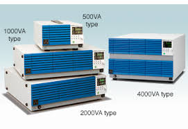
> AC Power Sources / Power Analyzers Keysight offers two families of AC power sources up to 4000 VA to meet your AC test challenges – from basic to higher performance. The AC6800 Series of basic AC sources offer stable, reliable power with models available up to 4000 VA. The 6800B Series of performance AC sources provide a complete AC test solution with integrated waveform generation and harmonic capabilities, at power levels up to 1750 VA. Both families may also be used to produce DC power, either alone or as a DC offset to an AC waveform. All models are backed with global support and the longest standard warranty in the industry. Compare All AC Power Sources (7) Find an AC Power Source Compare All AC Power Sources Accessories & Related Products AC6801A Basic AC Power Source, 500 VA, 270 V, 2.5 A 500 VA, 270 V, 2.5 A basic AC power source LAN/LXI-Core, USB, GPIB (optional) AC6802A Basic AC Power Source, 1000 VA, 270 V, 5 A

1000 VA, 270 V, 5 A basic AC power source AC6803A Basic AC Power Source, 2000 VA, 270 V, 10 A 2000 VA, 270 V, 10 A basic AC power source AC6804A Basic AC Power Source, 4000 VA, 270 V, 20 A 4000 VA, 270 V, 20 A basic AC power source
how much does it cost to replace a residential ac unit 6811B AC Power Source / Power Analyzer, 375 VA, 300 V, 3.25 A
ac unit will not come on 375 VA, 300 V, 3.25 A performance AC source
electricity cost of window ac unit Integrated waveform generation and harmonics 6812B AC Power Source / Power Analyzer, 750 VA, 300 V, 6.5 A 750 VA, 300 V, 6.5 A performance AC source 6813B AC Power Source / Power Analyzer, 1750 VA, 300 V, 13 A 1750 VA, 300 V, 13 A performance AC source

Discontinued AC Power Sources / Power Analyzers [Discontinued] Product support information for discontinued and obsolete AC Power Sources / Power Analyzers. Related Industries & TechnologiesAcopian Power Supply Literature Downloads Design Your Own Custom Power Supply - Use the Acopian Online System Builder AutoCAD & 3D CAD Drawings Custom Multiple Output Power Systems Built and Shipped Within 9 Days! Use the online System Builder or call us at 1-800-523-9478 to specify the output voltages, currents and any other operating features that you require.New ArticlesMOSFET as a SwitchRelationship of Line and Phase Voltages and Currents in a Star Connected System555 Timer and 555 Timer WorkingBistable MultivibratorMonostable MultivibratorAstable MultivibratorClosely Related ArticlesOp-amp | Working Principle of Op-ampAmplifier Gain | Decibel or dB GainIntegrated Circuits | Types of ICRegulated Power SupplyLaser | Types and Components of LaserWork FunctionInverting AmplifierMobility of Charge CarrierWhat are Photo Electrons?

Electron volt or eVEnergy Quanta | Development of Quantum Physics Wave Particle Duality PrincipleHeisenberg Uncertainty PrincipleSchrodinger Wave Equation and Wave FunctionCyclotron Basic Construction and Working PrincipleDiode | Working Principle and Types of DiodeDiode CharacteristicsWhat is Zener Diode?Application of Zener DiodeVacuum Diode History Working Principle and Types of Vacuum Diodep-n Junction Diode and Characteristics of p-n JunctionFull Wave Diode RectifierHalf Wave Diode RectifierP-I-N Photodiode | Avalanche Photo DiodeLED or Light Emitting DiodeTunnel Diode and its ApplicationsGUNN DiodeVaractor DiodeLaser DiodeFull Wave RectifiersBridge RectifiersMOSFET | Working Principle of p-channel n-channel MOSFETMOSFET CircuitsMOS Capacitor | MOS Capacitance C V CurveApplications of MOSFETMOSFET as a SwitchDiode Bridge RectifierTheory of SemiconductorIntrinsic SemiconductorExtrinsic SemiconductorsEnergy Bands of SiliconDonor and Acceptor Impurities in Semiconductor Conductivity of SemiconductorCurrent Density in Metal and Semiconductor Intrinsic Silicon and Extrinsic SiliconP Type SemiconductorN Type SemiconductorP N Junction Theory Behind P N JunctionForward and Reverse Bias of P N JunctionZener BreakdownAvalanche BreakdownHall Effect Applications of Hall EffectBipolar Junction Transistor or BJT |

N-P-N or P-N-P Transistor Application Theory Biasing AmplifierApplications of Bipolar Junction Transistor or BJT | History of BJTBiasing of Bipolar Junction Transistor | BJT or Bipolar Transistor BiasingJFET or Junction Field Effect TransistorQuestions on JFET or Junction Field Effect TransistorDIAC Construction Operation and Applications of DIACTRIACTransistor as SwitchApplication of Field Effect TransistorTypes of TransistorsTransistor CharacteristicsTransistor BiasingPhototransistorn-channel JFET and p-channel JFET Today almost every electronic device needs a dc supply for its smooth operation and they need to be operated within certain power supply limits. This required dc voltage or DC supply is derived from single phase ac mains.A regulated power supply can convert unregulated an ac (alternating current or voltage) to a constant dc (direct current or voltage). A regulated power supply is used to ensure that the output remains constant even if the input changes. A regulated DC power supply is also called as a linear power supply, it is an embedded circuit and consists of various blocks.
The regulated power supply will accept an ac input and give a constant dc output. Figure below shows the block diagram of a typical regulated dc power supply. The basic building blocks of a regulated dc power supply are as follows: A step down transformer Operation of Regulated Power Supply A step down transformer will step down the voltage from the ac mains to the required voltage level. The turn’s ratio of the transformer is so adjusted such as to obtain the required voltage value. The output of the transformer is given as an input to the rectifier circuit. Rectifier is an electronic circuit consisting of diodes which carries out the rectification process. Rectification is the process of converting an alternating voltage or current into corresponding direct (DC) quantity. The input to a rectifier is ac whereas its output is unidirectional pulsating dc. Usually a full wave rectifier or a bridge rectifier is used to rectify both the half cycles of the ac supply (full wave rectification).

Figure below shows a full wave bridge rectifier. A bridge rectifier consists of four p-n junction diodes connected in the above shown manner. In the positive half cycle of the supply the voltage induced across the secondary of the electrical transformer i.e. VMN is positive. Therefore point E is positive with respect to F. Hence, diodes D3 and D2 are reversed biased and diodes D1 and D4 are forward biased. The diode D3 and D2 will act as open switches (practically there is some voltage drop) and diodes D1 andD4 will act as closed switches and will start conducting. Hence a rectified waveform appears at the output of the rectifier as shown in the first figure. When voltage induced in secondary i.e. VMN is negative than D3 and D2 are forward biased with the other two reversed biased and a positive voltage appears at the input of the filter. The rectified voltage from the rectifier is a pulsating DC voltage having very high ripple content. But this is not we want, we want a pure ripple free dc waveform.

Hence a filter is used. Different types of filters are used such as capacitor filter, LC filter, Choke input filter, π type filter. Figure below shows a capacitor filter connected along the output of the rectifier and the resultant output waveform. As the instantaneous voltage starts increasing the capacitor charges, it charges till the waveform reaches its peak value. When the instantaneous value starts reducing the capacitor starts discharging exponentially and slowly through the load (input of the regulator in this case). Hence, an almost constant dc value having very less ripple content is obtained. This is the last block in a regulated DC power supply. The output voltage or current will change or fluctuate when there is change in the input from ac mains or due to change in load current at the output of the regulated power supply or due to other factors like temperature changes. This problem can be eliminated by using a regulator. A regulator will maintain the output constant even when changes at the input or any other changes occur.

Transistor series regulator, Fixed and variable IC regulators or a zener diode operated in the zener region can be used depending on their applications. IC’s like 78XX and 79XX are used to obtained fixed values of voltages at the output. With IC’s like LM 317 and 723 etc we can adjust the output voltage to a required constant value. Figure below shows the LM317 voltage regulator. The output voltage can be adjusted with adjusting the values of resistances R1 and R2. Usually coupling capacitors of values about 0.01µF to 10µF needs to be connected at the output and input to address input noise and output transients. Ideally the output voltage is given by Figure below shows the complete circuit of a regulated +5V DC power supply usingTypes of ICLaser | Types and Components of LaserWhat are Photo Electrons? Development of Quantum Physics Schrodinger Wave Equation and Wave FunctionCyclotron Basic Construction and Working PrincipleDiode | Working Principle and Types of DiodeVacuum Diode History Working Principle and Types of Vacuum Diodep-n Junction Diode and Characteristics of p-n JunctionP-I-N Photodiode |