ac power supply how it works
In this tutorial we will explain everything you need to know about PC power supplies, including form factors, efficiency, power factor correction (PFC), rails, protections, ripple and much more. You will learn that the power supply power rating should not be the only factor to consider when buying a power supply unit. But before going further, let’s explain exactly what a power supply does. As an electrical device, the computer needs power in order for its components to operate properly. The device responsible for supplying power to the computer is the power supply. In short, we could say that the main function of the power supply is to convert alternating voltage (a.k.a. AC), which is supplied by the electrical power system into continuous voltage (a.k.a. DC). In other words, the power supply converts the conventional 110V or 220V alternating voltage into continuous voltage used by the PC electronic components, which are +3.3 V, +5 V, +12 V and -12 V (Alternating voltages vary throughout the world.

In this tutorial, we will use “110 V” as a catchall label for 110 V, 115 V and 127 V voltages, whereas we will use “220 V” as a catchall label for 220 V, 230 V and 240 V voltages. Japan, which uses a 100V power grid, is the only country outside this range.) The power supply is also present in the PC cooling process, as we will explain in detail later. There are two basic power supply designs: linear and switching-mode. Linear power supplies work by getting the 110 V or 220 V from the power grid and lowering its value (e.g., 12 V) by using a transformer. This lower voltage is still AC. Then rectification is done by a set of diodes, transforming this AC voltage into pulsating voltage. The next step is filtering, which is performed by an electrolytic capacitor, transforming this pulsating voltage into almost DC. The DC obtained after the capacitor oscillates a little (this oscillation is called ripple), so a voltage regulating stage is necessary, made by a zener diode (frequently with the aid of a power transistor) or by a voltage regulator integrated circuit.

After this stage the output is true DC voltage. Although linear power supplies work very well for several low-power applications – cordless phones is an application that comes to mind – when high power is needed, linear power supplies can be very large. The size of the transformer and the capacitance (and thus the size) of the electrolytic capacitor are inversely proportional to the frequency of the input AC voltage; the lower the AC voltage frequency, the bigger the size of those components and vice-versa. Since linear power supplies still use the 60 Hz (or 50 Hz, depending on the country) frequency from the power grid (which is a very low frequency), the transformer and the capacitor are huge. Building a linear power supply for the PC would be insane, since it would be very big and heavy. The solution was to use the high-frequency switching approach. On high-frequency switching mode power supplies (a.k.a. SMPS), the input voltage has its frequency increased before going into the transformer (in the range of kHz are typical values).

With input voltage frequency increased, the transformer and the electrolytic capacitors can be very small. This is the kind of power supply used on the PC and several other types of electronic equipment, such as DVD players.
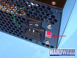
car ac repair dealsKeep in mind that “switching” is short for “high-frequency switching,” which has nothing to do with whether the power supply has an on/off switch or not…
how do i know how big my ac unit is The power supply is probably the most neglected component on PC.
cover for central ac unitUsually when buying a computer, we just take on account the processor type and clock, the motherboard model, the video card model, the quantity of installed memory, the hard disk storage capacity, and we forget about the power supply, which, in fact, is the one who supplies the “fuel” for the PC parts to operate properly.
A power supply of good quality and with enough capacity can increase the durability of your equipment and reduce your electricity bill (we will explain why when discussing efficiency). Just to get an idea, a high-quality power supply will cost less than 5% of the PC total price. On the other hand, a low-quality power supply can cause several intermittent problems, most of which are difficult to solve. A defective or bad-intentioned power supply can lock the PC, result in hard disk bad blocks, cause the infamous “blue screen of death” errors, andgive rise to random resets and freezings, added to many other problems. In this tutorial, we will discuss the basics that every user should know. If you want to learn even more about the internals of a PC power supply we recommend that after reading this tutorial, you read its sequel, Anatomy of Switching Power Supplies, where we explain in detail how the major internal components of a PC power supply work.These guys are everywhere - all sorts of voltage and current ratings.

They're available for sale at any store just about, but there are some big things to watch out for! One is that the output voltage is not going to be 9V (for example) out of the box, that voltage rating is just the minimum output for the current rating (200mA for example). And also, the output is going to have a lot of ripple on it! Before we talk precisely about these guys, lets go back in time to when engineers had to build their power supplies with their bare hands! The good old days! check out the wikipedia page. and the other half would output 12V AC (the 'secondary' 'low side'). The transformer functioned in two ways: one it took the dangerous high voltage and transformed it to a much safer low voltage, second itisolated the two sides. That made it even safer because there was no way for the hot line to show up in your electronics and possibly electrocute you. We'll use a schematic symbol to indicate a transformer, its two coils inside which are drawn out, the schematic symbol will have the same number of coils on either side so use common sense and any schematic indicators to help you out in figuring which is primary and which is secondary!

power diode such as a 1N4001 What we have now isnt really AC and isn't really DC, its this lumpy wave. The good news is that it's only positive voltage'd now, which means its safe to put a capacitor on it. This is a 2200 microFarad (0.0022 Farad) capacitor, one leg has (-) signs next to it, this is the negative side. The other side is positive, and there should never be a voltage across is so that the negative pin is 'higher' than the positive pin or it'll go POOF! Because the voltage is very uneven (big ripples), we need a really big electrolytic-type capacitor. Well, there's a lot of math behind it which you can read about but the rough formula you'll want to keep in mind is: Ripple voltage = Current draw / ( (Ripple frequency) * (Capacitor size) )or written another way Capacitor size = Current draw / ( (Ripple frequency) * (Ripple Voltage) )For a half wave rectifier (single diode) the frequency is 60 Hz (or 50 Hz in europe). The current draw is how much current your project is going to need, maximum.
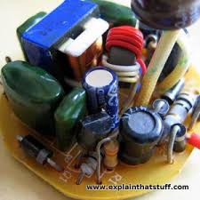
The ripple voltage is how much rippling there will be in the output which you are willing to live with and the capacitor size is in Farads. So lets say we have a current draw of 50 mA and a maximum ripple voltage of 10mV we are willing to live with. For a half wave rectifier, the capacitor should be at least = 0.05 / (60 * 0.01) = 0.085 Farads = 85,000 uF! This is a massive and expensive capacitor. For that reason, its rare to see ripple voltages as low as 10mV. Its more common to see maybe 100mV of ripple and then some other technique to reduce the ripple, such as a linear regulator chip. You don't have to memorize that formula, but you should keep the following in mind: When the current goes up and the capacitor stays the same, the ripple goes up. If the current goes up and you want the ripple the same, the capacitor must also increase. The transformer AC/DC in practice Wow so this looks really familiar, right? From let to right, you can see the wires that come into the transformer from the wall plug, the transformer output has two power diodes on it and a big capacitor (2,200uF).

You might be a little puzzled at the two diodes - shouldn't there be four for a full-wave rectifier? It turns out that if you have a special transformer made with a 'center tap' (a wire that goes to the center) you can get away with using only two diodes . So it really is a full wave rectifier, just one with a center-tap transformer. These transformer-based plug-packs are really cheap to make - like on the order of under $1! Testing the 9V supply Let's look in detail With 35 ohms (230 mA draw) the voltage plummets to 7.7V! As the resistance gets smaller and smaller, the current draw gets higher and higher and the voltage droops (that's the technical term for it!) You can also see the ripple increase as the current goes up. Now we can at least understand the thinking behind saying "9V 200mA" on the label. As long as we are drawing less than 200mA the voltage will be higher than 9V. What does this mean for you?OK so after all that work, you're wondering why does this even matter?

The reason it matters is that everywhere you look are these wall warts that are 'unregulated' and thus extremely suspicious. You simply can't trust 'em to give you the voltage you want!For example, lets say you have a microcontroller project and it requires 5V power as many DIY projects do. You shouldn't go out and buy a 5V transformer supply like the one above and just stick the power output into your microcontroller - you'll destroy it! Instead, you will need to build a 5V regulator like the common LM7805 that will take the somewhere-around-9V from the transformer and convert it to a nice steady 5V with almost no ripple. So here is what you should always do: Always check your power supply brick with a multimeter to see what the maximum voltage is Assume that the voltage can be twice as high as you expect Assume that the voltage will droop as you draw more and more current If you're using a brick for low-power usage, say your circuit draws 100mA max, find one that has a very similar current rating.

You might be wondering well why on earth doesn't someone make a power plug that takes a transformer and some diodes and a LM7805 and that will give you a nice 5V output instead of having everyone build it into the project circuit? While its an interesting idea there are a few reasons they don't do that. One is that the enclosed wall adapter would overheat. Another is that some projects need more than one voltage, say 5V and 3.3V both. But in the end, its probably for manufacturing simplicity. The factory that makes the wall plugs makes 100's of thousands in predictable sizes and rates, each country has plenty of factories to make the right plug packs for the wall voltage and plug style. The designers of, say, the DVD player have an easier time of it when they can just say "anything above 7V and below 20V input will work for us" and the plug-pack maker matches them up with the closest thing they already make. Nowadays, there are switch-mode power plugs that solve much of this problem.