ac power supply circuit design
404 Error File Not Found The page you are looking for might have been removed, had its name changed, or is temporarily unavailable.How Power Supplies Turn AC into DC in Electronic Circuits The task of turning alternating current into direct current is called rectification, and the electronic circuit that does the job is called a rectifier. The most common way to convert alternating current into direct current is to use one or more diodes, those handy electronic components that allow current to pass in one direction but not the other. Although a rectifier converts alternating current to direct current, the resulting direct current isn’t a steady voltage. It would be more accurate to refer to it as “pulsating DC.” Although the pulsating DC current always moves in the same direction, the voltage level has a distinct ripple to it, rising and falling a bit in sync with the waveform of the AC voltage that’s fed into the rectifier. For many DC circuits, a significant amount of ripple in the power supply can cause the circuit to malfunction.
Therefore, additional filtering is required to “flatten” the pulsating DC that comes from a rectifier to eliminate the ripple. There are three distinct types of rectifier circuits you can build: half-wave, full-wave, and bridge. The following describes each of these three rectifier types. The simplest type of rectifier is made from a single diode. This type of rectifier is called a half-wave rectifier because it passes just half of the AC input voltage to the output.
how long should an outdoor ac unit last When the AC voltage is positive on the cathode side of the diode, the diode allows the current to pass through to the output.
ac unit for sale usedBut when the AC current reverses direction and becomes negative on the cathode side of the diode, the diode blocks the current so that no voltage appears at the output.
new outdoor ac unit cost
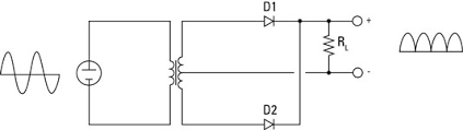
Half-wave rectifiers are simple enough to build but aren’t very efficient. That’s because the entire negative cycle of the AC input is blocked by a half-wave rectifier. As a result, output voltage is zero half of the time. This causes the average voltage at the output to be half of the input voltage. Note the resistor marked RL. This resistor isn’t actually a part of the rectifier circuit. Instead, it represents the resistance imposed by the load that will ultimately be placed on the circuit when the power supply is put to use. A full-wave rectifier uses two diodes, which enables it to pass both the positive and the negative side of the alternating current input. The diodes are connected to the transformer. Notice that the full-wave rectifier requires that you use a center-tapped transformer. The diodes are connected to the two outer taps, and the center tap is used as a common ground for the rectified DC voltage. The full-wave rectifier converts both halves of the AC sine wave to positive-voltage direct current.

The result is DC voltage that pulses at twice the frequency of the input AC voltage. In other words, assuming the input is 60 Hz household current, the output will be DC pulsing at 120 Hz. The problem with a full-wave rectifier is that it requires a center-tapped transformer, so it produces DC that’s just half of the total output voltage of the transformer. A bridge rectifier overcomes this limitation by using four diodes instead of two. The diodes are arranged in a diamond pattern so that, on each half phase of the AC sine wave, two of the diodes pass the current to the positive and negative sides of the output, and the other two diodes block current. A bridge rectifier doesn’t require a center-tapped transformer. The output from a bridge rectifier is pulsed DC, just like the output from a full-wave rectifier. However, the full voltage of the transformer’s secondary coil is used. You can construct a bridge rectifier using four diodes, or you can use a bridge rectifier IC that contains the four diodes in the correct arrangement.
A bridge rectifier IC has four pins: two for the AC input and two for the DC output.Here’s the page we think you wanted. See search results instead: 0-50W, DC Power Supplies, Single and Multiple Outputs 25-50W, DC System Power Supplies, GPIB, Multiple Outputs > U3002A Analog Circuit Design Teaching Solution U3002A Analog Circuit Design Teaching Solution Authorized Sales Partners - Check availability U3002A Analog circuit design U3002A-TR2 Electronic circuit design courseware, with training kit and teaching slides Typically Configured Price US$ 1,904 How to Buy or Rent Prices for: United States * Prices are subject to change without notice. Prices shown are Manufacturer's Suggested Retail Prices (MSRP). Prices shown are exclusive of taxes. Integrated curriculum with a complete set of instruments, instructor’s guide, training kits and lab worksheets. Editable teaching material in MS PowerPoint format for lecturers.

The lab sheets enable students to appreciate different design considerations and approaches by allowing them to experiment with different components. The teaching solution is a ready-to-teach package targeting 3rd or final year undergraduates. This solution focuses on the areas of practical analog circuit analysis, design, and its applications. It is a great tool for students to understand analog circuit analysis, practical op-amp design, active filter design and measurement instruments usage. This courseware is designed to impart knowledge in: Passive and active components BJT circuit analysis and design The complete solution setup includes the following instruments: U2761A USB Modular Function Generator U2741A USB Modular Digital Multimeter U2701A USB Modular Oscilloscope The University Teaching Solution is also available with bench options. Substitute the USB modular instruments U2701A, U2741A and U2761A with their bench counterpart: DSO1000 series oscilloscope, 34405A digital multimeter and 33210A/33220A function/arbitrary waveform generator respectively.