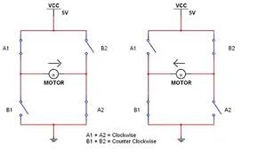
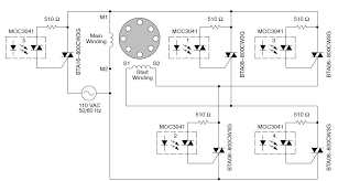
ac motor control circuit

A.C. motor control circuitOthers with the same file for datasheet: Download HEF4752VP datasheet from PhilipsHow Do Servo Motors Work This little motor is high in efficiency and power Servo motors have been around for a long time and are utilized in many applications. They are small in size but pack a big punch and are very energy-efficient. These features allow them to be used to operate remote-controlled or radio-controlled toy cars, robots and airplanes. Servo motors are also used in industrial applications, robotics, in-line manufacturing, pharmaceutics and food services. But how do the little guys work? The servo circuitry is built right inside the motor unit and has a positionable shaft, which usually is fitted with a gear (as shown below). The motor is controlled with an electric signal which determines the amount of movement of the shaft. What's inside the servo? Hitec HS-322HD Standard Heavy Duty Servo To fully understand how the servo works, you need to take a look under the hood.

Inside there is a pretty simple set-up: a small DC motor, potentiometer, and a control circuit. The motor is attached by gears to the control wheel. As the motor rotates, the potentiometer's resistance changes, so the control circuit can precisely regulate how much movement there is and in which direction.
ac unit for trailer home When the shaft of the motor is at the desired position, power supplied to the motor is stopped.
air conditioning units for log cabinsIf not, the motor is turned in the appropriate direction.
car a/c leak testThe desired position is sent via electrical pulses through the signal wire. The motor's speed is proportional to the difference between its actual position and desired position. So if the motor is near the desired position, it will turn slowly, otherwise it will turn fast.

This is called proportional control. This means the motor will only run as hard as necessary to accomplish the task at hand, a very efficient little guy. How is the servo controlled? The guts of a servo motor (L) and an assembled servo (R) Servos are controlled by sending an electrical pulse of variable width, or pulse width modulation (PWM), through the control wire. There is a minimum pulse, a maximum pulse, and a repetition rate. A servo motor can usually only turn 90 degrees in either direction for a total of 180 degree movement. The motor's neutral position is defined as the position where the servo has the same amount of potential rotation in the both the clockwise or counter-clockwise direction. The PWM sent to the motor determines position of the shaft, and based on the duration of the pulse sent via the control wire; the rotor will turn to the desired position. The servo motor expects to see a pulse every 20 milliseconds (ms) and the length of the pulse will determine how far the motor turns.

For example, a 1.5ms pulse will make the motor turn to the 90-degree position. Shorter than 1.5ms moves it to 0 degrees, and any longer than 1.5ms will turn the servo to 180 degrees. Variable Pulse width control servo position When these servos are commanded to move, they will move to the position and hold that position. If an external force pushes against the servo while the servo is holding a position, the servo will resist from moving out of that position. The maximum amount of force the servo can exert is called the torque rating of the servo. Servos will not hold their position forever though; the position pulse must be repeated to instruct the servo to stay in position. Types of Servo Motors There are two types of servo motors - AC and DC. AC servo can handle higher current surges and tend to be used in industrial machinery. DC servos are not designed for high current surges and are usually better suited for smaller applications. Generally speaking, DC motors are less expensive than their AC counterparts.

These are also servo motors that have been built specifically for continuous rotation, making it an easy way to get your robot moving. They feature two ball bearings on the output shaft for reduced friction and easy access to the rest-point adjustment potentiometer. Servos are used in radio-controlled airplanes to position control surfaces like elevators, rudders, walking a robot, or operating grippers. Servo motors are small, have built-in control circuitry and have good power for their size. In food services and pharmaceuticals, the tools are designed to be used in harsher environments, where the potential for corrosion is high due to being washed at high pressures and temperatures repeatedly to maintain strict hygiene standards. Servos are also used in in-line manufacturing, where high repetition yet precise work is necessary. Of course, you don't have to know how a servo works to use one, but as with most electronics, the more you understand, the more doors open for expanded projects and projects' capabilities.
Whether you're a hobbyist building robots, an engineer designing industrial systems, or just constantly curious, where will servo motors take you? Servo Motor Buyer Guide If you have an electronics story or project you'd like to share, please email .Most of this website is devoted to active semiconductors and electronics controlling DC motors. For example, many of the robots have microcontrollers that drive motor direction through a transistor H-bridge. However, sometimes you want a very basic solution where a person can directly operate a motor with a flick of a switch. This can be easily accomplished. The first thing you need to test is the battery and motor. This will eliminate any problems with them before you add the complexity of one or more switches to the circuit. These tests are easiest to perform with alligator clips, if you have them. Forward and backward motor and battery wiring diagram. A red wire is shown because a white wire won’t show up on a white background.

If the motor doesn’t turn, check the connections. It could also be that the battery voltage is too low or the battery is dead. If the motor turns too fast, trade down to a lower voltage battery or get a motor with a gearhead. You must have a motor and battery that passes steps 2 and 3 of the test before continuing. Obviously you don’t want to have to rewire your motor every time to turn it off or change directions. We’re going to let the switch do that. Inside the switch there are metal strips that either connect the wires or disconnect them, as the lever is flipped back and forth. Here are the wire assignments: Solder the white (power positive) wires to the DPDT switch. 1. Connect the white wire (positive power) to the DPDT switch as shown above. You'll need one long piece of wire coming from the battery to the first switch terminal. And, you'll need a smaller piece of wire coming from the first switch terminal to the opposite terminal as shown.

Solder the black (power negative) wires to the DPDT switch. 2. Connect the black wire (negative power) to the DPDT switch as shown above. You'll need one long piece of wire coming from the battery to the lower switch terminal. And, you'll need a smaller piece of wire coming from the lower switch terminal to the opposite terminal as shown. Solder the yellow and blue motor wires to the DPDT switch. 3. Connect the yellow and blue wires from the motor to the center terminals of the DPDT switch as shown above. 4. Connect the yellow and blue wires to the motor terminals. 5. Make sure the switch is in the center (off) position, before connecting the battery. 6. Connect the white and black wires to the battery. Wiring can be a bit of a pain. You can use a small printed circuit board instead (particularly if you're going to wire more than one switch). Click on the file and save it. Download Copper Connection, the PCB layout software.

Free to display, edit, and etch at home. Let’s step through what happens when you flip the switch to the top, center, and bottom... Lack of connections in a DPDT switch, resulting in a turned-off motor. When the switch lever is in the middle position, the motor is off because the metal inside the switch is not connecting the wires from the middle terminals (the motor) to any of the outer terminals (the power source). This is the same as if you simply disconnected the wires to the battery. No power is being used. Connections in a DPDT switch, resulting in a motor going forward. When the switch lever is in the top position, the motor rotates forward. If your motor rotates in the opposite direction than you expected or wanted, simply reorient the switch in your hand so that lever is facing the bottom, and then toggle the lever to the top. Alternatively, you could swap the wires on either the battery terminals or the motor terminals. Inside the switch, the lever has pushed metal strips such that the motor wires on the middle terminal are electrically connected to one pair of the outer terminals leading to the battery.
The term “double pole” refers to that fact that this switch has a pair of terminals that it connects or disconnects at the same time. If we only needed a single wire to be connected or disconnected, we could use a single pole (SP) switch. Connections in a DPDT switch resulting in a motor going backward. When the switch lever is in the bottom position, the motor rotates backward. Inside the switch, the lever has pushed metal strips such that the motor wires on the middle terminal are electrically connected to the other pair of the outer terminals leading to the battery. Notice that the black and white battery wires are on opposite sides on the top and bottom switch terminals. That’s why the motor rotates in the opposite direction. The term “double throw” refers to that fact that this switch can be thrown to the top and thrown to the bottom (two different throws). If we only needed the motor to go forward or turn off, we could use a single throw (ST) switch.

If your motor doesn’t operate correctly, double check that the wires go to the correct switch terminals. Also, make sure the wiring isn’t loose or broken. Use a magnifying glass to make sure not even a tiny strand of wire is accidentally touching another wire or terminal. Being able to control a motor directly is useful. But, sometimes you won’t be paying attention and the item connected to the motor will crash into a barrier or otherwise exceed its maximum position. It would be nice to add a couple of additional switches to automatically stop the motor when it has gone too far, but still allow the operator to return the motor to an allowed position. Wiring diagram of a DPDT connected motor plus two snap-action switches for user control with limit stops. The wiring diagram above is similar to the ones shown earlier. Two additional switches have been inserted. One switch connects (or disconnects) the white wire on the bottom terminal.

The other switch connects (or disconnects) the black wire on the top terminal. Snap action switches have been put to good use in my Flip-Flop robot. If you’re not familiar with those types of switches, take a quick look at the pictures and watch the video. The idea is that each snap-action switch is wired such that their respective wire is normally connected (NC) just as it was in earlier diagrams. This allows the user’s DPDT switch to operate as usual. However, when something presses against the snap-action switch, it disconnects the wire, cutting off power in that direction only. If the user throws the lever into the opposite direction, the other snap-action switch is not being pressed against, and so it allows the motor to reverse. If you mounted a motorized device on a linear (straight) track and placed each snap-action switch on opposite ends of the track, you could throw the switch in one direction and the device would automatically stop when it reached the end of the track.

You could then throw the switch in the opposition direction, and the device would proceed to the other end of the track before stopping. Similarly, you could add a pin or arm to a disc, which would press against a snap-action switch when the motor shaft rotated to the desired angle. This article demonstrates how to change directions on a small motor from a consumer battery source using a DPDT center-off switch. There are many uses and variations for such a circuit. It is possible to use more powerful motors and greater power sources. The biggest limitation will be finding a physical switch that can handle enough current and voltage. You must be sure that the manufacturer rates the switch for at least the maximum power you intend to use. In fact, a superior design would be to connect a low-rated switch with a weak power source to a relay with a higher power source. A relay is a magnetically-activated switch that acts as proxy, echoing what the user is doing with the lower-power switch.

Over time, a switch connected to a large motor or power source will burn out due to electrical arcs when making or breaking electrical connections. Another concern with large motors (particularly when hooked up to equipment) is sudden starting and stopping. Momentum can be a killer. Speed controls or digital pulse-width modulation techniques can gently ramp up or ramp down hefty motors. Overall, the most serious concern with large motors or significant power sources (such as AC outlets) is safety. That’s why these things should be left to professional equipment with the proper enclosures, redundant limit sensors, and independently certified testing. That being said, this DPDT switch should work comfortably with small DC motors and battery sources, such as in models, toy trains, and hobby robots. To learn about intelligent motor control using semiconductors (transistors), see Chapters 9 and 10 of Intermediate Robot Building or look through the many articles on this site.