ac dc power supply reference design
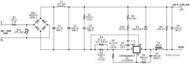
Home » News » Products » LED Lighting Capable of working from inputs from 90 to 305Vac, it is triac (and trailing-edge) dimmable on nominal 110V supplies, but not on 230V supplies. The dimming voltage is a clue here – this chip is aimed at commercial US installations where mains is split-phase and either 110V or double this. A future version will be optimised for dimming at 230V. Called LYTSwitch-7, the firm claims dimmer compatibility without a bleeder resistor. “Designs do not require bleeders; employing simple, passive damping for TRIAC management,” said the firm. 86% efficiency is claimed for 230V operation – this is from a reference design called DER-561 (included in the data sheet) which is for a 7.5W design feeding 60V of LEDs from a 185-300V supply. Current regulation is +/-3% and efficiency stays above 80% right across the range. This design, using the LYT7503D, actually works up from 90V, and is dimmable at lower voltages. Power factor is 0.9.

Even though the package is an SO-8, operation has been stretched to 22W loads in some designs by allocating four pins to the mosfet source for conductive heatsinking. Space was freed-up by combining several control functions into a single pin, now called the multi-function pin. The integrated mosfet is rated at 725V, and the main power inductor is a simple two-terminal inductor rather than a tapped inductor or transformer. 20 components total are required for a light bulb design. “A 725V mosfet delivers better withstand performance during line surges,” said Huberto Notohamiprodjo, director of product marketing at Power Integrations. The firm has gone for a linear dimming curve rather than logarithmic, claiming that this is more power efficient and arguing that acceptability testing indicates users are happy a wide range of dimming curves so long as there is always some visible change of brightness when ever the control is moved. Protection includes: automatic LED dimming if the bulb is over-heating (followed by shut-down if the temperature continues to rise), open-circuit, short-circuit, input over-voltage, output over-voltage, over-current and safe operating area (SOA).

“LYTSwitch-7 ICs meet international standards including: DOE Level 6 (external power supply), CEC Titles 20 and 24, Energy Star Lamps Program Requirements Version 2.0, NEMA SSL-7A and EN61000-3-2 C and D,” said the firm.
removing ac unit from car The output current has a high ripple factor, leading to 100 or 120Hz strobing.
in wall hvac systems“The LYSTwitch-7 can be paired with external ripple-reduction circuits to achieve low output ripple in applications or geographies that may require it, the very high efficiency of LYTSwitch-7 is helpful in reducing the impact on efficiency that these circuits have,” said Power Integrations’ director of training Andrew Smith.
hvac heat pump efficiency As the design is non-isolated, applications are expected where users cannot touch the LEDs – inside light bulbs and sealed luminaires.

Three reference designs have been prepared, all dimmable and non-isolated: DER-561: 7.5W, 60V, 125mA output 90-300Vac A19 bulb (dimming 110Vac only) DER-539: 6.24W 52V 120mA output 90-132Vac A19 bulb DER-540: 4.68W 52V 90mA output 90-132Vac candelabra bulb Tagged with: Power Integrations Get Electronics Weekly every day Power Supply with 1 kV MSOP Isolators This circuit is for an approximately 2.5W switch-mode power supply. isolates the synchronous rectification. A simple pulse-width modulator digitizes the output voltage and an inherently failsafe IL610-1 isolator provides isolated feedback for the output voltage. The IL610-1 replaces the linear optocoupler typically used for this purpose, eliminated a major reliability problem. The MSOP-8 isolators minimize board area. The IL711’s 0.3 ns pulse-width distortion and 100 ps jitter improve precision, minimize MOSFET dead time, and maximize system efficiency. Digital-Feedback Switch-Mode Power Supply with 2.5 kV MSOP

MSOP 2.5 kV Isolator isolates the synchronous rectification. convertor digitizes the output voltage, and an IL710V-1 provides isolated feedback for the output voltage. A one shot serves as a frequency-to-voltage convertor to provide output voltage feedback. The IL710V-1 replaces the linear optocoupler typically used for this purpose, eliminated a major reliability problem. The MSOP isolators minimize board area. The isolators' pulse-width distortion and 100 ps jitter improve precision, minimize MOSFET dead time, and maximizeLow EMI, transient immunity of 50 kV/µs, and barrier life of 44000 years make IL700-Series isolators ideal for this application. Power Supply Gate Driver with an IL711 Isolator This circuit is for an approximately 100 W quarter-brick-scale power supply. An IL711V-1E isolates the LM5035CSQ PWM Controller from the LM5110 MOSFET gate driver for synchronous rectification. All of the key ICs in this reference design are small.

The LM5035CSQ is a WQFN-24; the LM5110 is available in a WSON-10, and the IL711 in an MSOP8). two-channels and full 2.5 kV isolation in an ultraminiature MSOP-8 package. Alternatively, the wide-body IL711VE provides 5 kV isolation and best-in-class 1 kV Working Voltage in a true 8 mm creepage package. The IL711’s 0.3 ns pulse-width distortion and 100 ps jitter improve precision, minimize MOSFET dead time, and maximize system efficiency. transient immunity of 50 kV/µs, and barrier life of 44000 years make IsoLoop isolators ideal for this application. Power Control Using IL610s The fail-safe output (logic high output for zero coil current) of IL600 Isolators ensures the power FETs will be off on power-up. The IL600 inputs can be configured for inverting or non-inverting operation (see IL600 Product Data Sheet). The IL600 Isolators provide 2.5 kVrms isolation (1 minute), and 20 kV/µs transient immunity. AC Line Monitor Using IL610A

The wide input voltage range of IL600 Isolators allows connection to line voltage through current-limiting resistors. Unlike optocouplers, input voltage can reverse without damaging the inputs. this illustrative circuit, “Monitor Out” goes low when line voltageThe 74HC123 monostable converts the 60 Hz isolator output to a monitor signal. Faster and longer networks should be be terminated. Reflections are minimized by terminating both ends of the bus but not every node. Two 120 ohm termination resistors (on each end of the bus) are used to match a 60 ohm cable impedance. With terminated networks the differential voltage across the conductor pair will be close to zero with no active drivers. In this case, the idle bus is indeterminate and susceptible to noise. External fail-safe biasing resistors (RFS-EXT) at one end of the bus ensure fail-safe operation with a terminated bus. Biasing should provide at least 200 mV across the conductor pair to meet the RS-485 input sensitivity specification.

The more loads on the bus, the lower the required values of the biasing resistors. The reference design has a 120 ohm termination resistor and 560 ohm biasing resistors for fail-safe operation for up to four Unit Loads. The 220 ohm termination resistor, along with another 220 ohm resistor and the other end of the bus, matches the bus impedance to minimize reflections. The 390 ohm “fail-safe” resistors guarantee a known state with no active transceivers. Bypass capacitors should be placed as close as possible to the appropriate IC. Passive-Input RS-485 Isolated Transceiver Reference Design NVE’s unique have current-mode inputs for maximum flexibility. reference design for a 3.3 V controller and 5 volt bus is shown above. Isolating the input to a USB controller (rather than the bus lines) requires fewer isolation channels, and is therefore usually the simplest solution as shown in this reference design: The Microchip MCP2200 is a USB 2.0 to UART Protocol Converter.

The IL712/IL721 Series are best-in-class bidirectional isolators with a remarkable 100 ps of jitter, and parts are available in unique MSOPs to reduce board space. Isolated CAN Transceiver With DC-DC Convertor Reference Design The IL41050 single-chip isolated CAN transceiver provides an isolated CAN interface in a single chip. The isolator operates on the 3.3 V microcontroller power supply, and a low-cost dc-dc convertor provides 5 V to power the bus side. The IL41050 can withstand 200 V transients on the bus; the PSM712 provides additional ESD protection if necessary. Designed for harsh CAN and DeviceNet environments, IL41050 transceivers have a -55 to +125�C operating range, transmit data dominant time-out, bus pin transient protection, thermal shutdown protection, short-circuit protection, 2,500 V isolation, and typical transient immunity of 30 kV/µs. Unique edge-triggered inputs improve noise performance. An innovative nonvolatile programmable power-up feature prevents unstable nodes.